® U.S. Registered Trademark
Copyright © 2000 Honeywell Inc. • All Rights Reserved
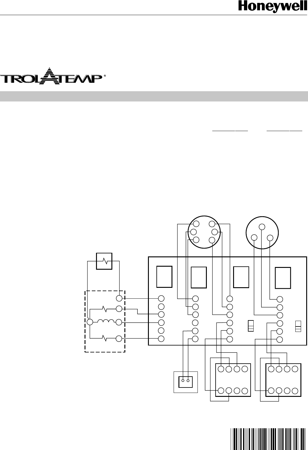
SCHEMATIC
MM-2 MASTERTROL®
MINI-ZONE™-2
69-1361
The Mastertrol® Mini-Zone™ -2 Zone Control Panel,
Model MM-2, controls 2 zones on any single stage
heating and cooling system. Each zone is controlled
by a thermostat which operates a motorized damper
in the zone duct to control the flow of conditioned air
to the zone. (Up to 2 dampers may be wired to a
single zone. When 3 or more dampers are required
a Slave Damper Control Relay, Model SDCR, is re-
quired.)
The Zone 1 Thermostat requires a manual
changeover subbase with “O” and “B” terminals. The
“O” terminal must make with R when the subbase is
switched to the COOL Mode. The “B” terminal must
make with R when the subbase is switched to the
HEAT Mode. When the Zone 1 Subbase in either the
Heat or Cool Mode, either zone thermostat can call
for the respective mode. The zone thermostat will en-
ergize it’s zone relay which activates the heating or
cooling controls, opens it’s zone damper and closes
the damper to the zone that is satisfied. When both
zone thermostats are satisfied the heating (or cool-
ing) will shut off and all zone dampers will return to
their normal position. The normal position of the zone
dampers is set by the OPEN/CLOSED (O/C) slide
switch next to the motor terminals.
SYSTEM CONNECTIONS: The MM-2
System Terminals, on the far left side of
the panel, wire to the HVAC Unit. These
terminals are isolated “dry” switching con-
tacts similar to any typical thermostat.
These terminals are wired to the HVAC
Unit the same as any thermostat would,
when not using this zone control panel.
The MM-2 connections used are typically
the RC-G-Y-W terminals wired the the
HVAC Unit Control Center.
HYDRO-AIR Systems - When using the
MM-2 with a Hydro-Air System, one
which uses a hot water coil in the air han-
dler to provide heating in place of a fur-
nace, the wiring is almost similar to that
shown. In this application the Heat Re-
lay shown may be a zone valve or circu-
lator relay. The Fan must be controlled
by an Aquastat. In order to bring the fan
on when the water in the coil is heated.
This is wired independently of the MM-2
panel.
OIL FURNACES - When using the MM-2 with an Oil
Fired Furnace to provide heating, the T and T termi-
nals on the Oil Burner Primary Control must wire to
the RH and W terminals, on the left side of the MM-
2.
NOTE: Once operational the Oil Furnace contin-
ues to run when all zones are satisfied, reverse the
RH and W wires on the MM-2.
DAMPER MOTOR WIRING - This diagram shows
Trol-A-Temp’s typical power open-power closed op-
posed blade damper motors. Note the jumper wire
required on the motor terminals 2 and 5. Round
Spring Return Dampers can also be wired to the
MM-2. When using the ARD-PC, wire to the M1 and
M6 terminals. When using the ARD-PO, wire to the
M1 and M4 terminals.
ZONE THERMOSTAT WIRING - The MM-2 can be
used with several different single stage thermostats.
The wiring shown is for the following recommended
thermostats:
Zone 1 Thermostat Zone 2 Thermostat
TRT(-W) and MCRS(-W) TRT(-W)/T87F
T8090T1003* T8090T1011*
T8602C T8602D
T8601C* T8603D*
*These thermostats may require additional wires.
Refer to the wiring information included with the ther-
mostat for complete information.
45
6
Z
12
3
X
ZONE 2 DAMPER MOTOR
T6/Y
T5/R
T4/W
45
6
Z
12
3
X
HVAC UNIT CONNECTIONS
M6
M4
M11
T6/Y
T5/R
T4/W
M6
M4
M1
O1
G1
B1
B
2
1
5/R
6/Y4/W
Y
G
R
MASTERTROL MINI - ZONE
24 VOLT 40 VA
TRANSFOMER
MODEL PMT-40
MODEL MM-2
MODEL DPBT
(T678A)
HEAT RELAY
ZONE 2 THERMOSTAT
ZONE 1 THERMOSTAT
AND SUBBASE
M13557
Y
O
G
RC
RH
W
Y
R
W
O
G
B
C
W
ZONE 1 DAMPER MOTOR
24 VOLT
TRANSFORMER
FAN RELAY
SYSTEM
ZONE 2
ZONE 1
O
C
O
C
RC


