


17
Gas Connections
The gas supply lines must meet all requirements of the National Fuel Gas Code
(ANSI Z223.1-Latest Edition), or in Canada CAN/CGA B149.1 Natural Gas
Installation Code (Latest Edition) or CAN/CGA B149.2 Propane Installation Code
(Latest Edition).
The minimum permissible gas supply pressure for the purpose of input adjustment is
one (1.0) inch (0.25 kPa) water column above the operating manifold pressure. See
the rating plate and gas valve for the manifold pressure and gas type. The maximum
permissible gas supply pressure is fourteen (14.0) inches (3.5 kPa) water column for
natural gas and liquefied petroleum gases/propane gas.
1. Connect this water heater only to the type of gas (Natural or Propane gas) as
shown on the rating plate. Use clean black iron pipe or equivalent material
approved by local codes and ordinances. (Dirt and scale from the pipe can enter
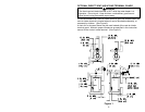
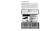
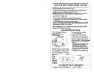
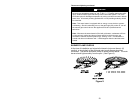
the gas valve and cause it to malfunction). The inlet gas line must have a
minimum length of three (3) inches (7.6 cm) drip leg (sediment trap) installed as
close to the water heater’s gas valve as possible. A ground joint union must be
installed as close to the water heater as possible in the gas supply line feeding
the water heater to permit servicing of the water heater. Compounds used on the
threaded joints of the gas piping must be resistant to the action of liquefied
petroleum gases/propane gas. DO NOT apply pipe dope to the gas valve inlet
and make certain that no pipe dope has become lodged in the inlet screen of the
gas valve. Extreme care must be taken to ensure no pipe dope enters the gas
valve. Avoid excessive torque when tightening the gas supply line to the gas
valve. Excessive torque may result in cracking of the gas valve housing and
could create a gas leak. When tightening gas supply line to L.P. control, it is
recommended to hold the inlet body of the control securely with an adequate
wrench. The suggested maximum torque is 31.5 ft. lbs. (4.4 kg-m).
2. This water heater and its gas connection must be leak tested before placing the
water heater in operation. Check for gas leaks with a soap and water solution
and a brush or a commercial leak detector fluid. NEVER USE A MATCH OR
OPEN FLAME FOR TESTING!
3. While checking for leaks care must be taken to prevent solution from
contacting the electrical connections at the control. If electrical connections at the
control become wet, they must be thoroughly dried before attempting to operate
the water heater.
WARNING
The manufacturer of this water heater will not be liable for any damage or injury
caused as a result of a cracked gas inlet as a result of excessive torque.
CAUTION
The water heater and individual shutoff valve must be disconnected from the gas
supply piping system during any pressure testing of the system at test pressures
in excess of 1/2 psi (3.5 kPa). The water heater must be isolated from the gas
supply piping system by closing its manual shutoff valve during any pressure
testing of the gas supply system at test pressures equal to or less than 1/2 psi
(3.5 kPa). The supply line must be capped when not connected to the water
heater.