


OUTDOOR UNIT
●
Please mount the Outdoor unit on stable ground to prevent vibration
and increase of noise level.
●
Decide the location for piping after sorting out the different types of
pipe available.
●
When removing side cover, please pull the handle after undoing the
hook by pulling it downward.
Removal Of Air From The Pipe And Gas Leakage Inspection
Gas Leakage Inspection
Please use gas leakage detector to check if leakage
occurs at the connection of Flare nut as shown on
the right.
If gas leakage occurs, further tighten the connection
to stop leakage.
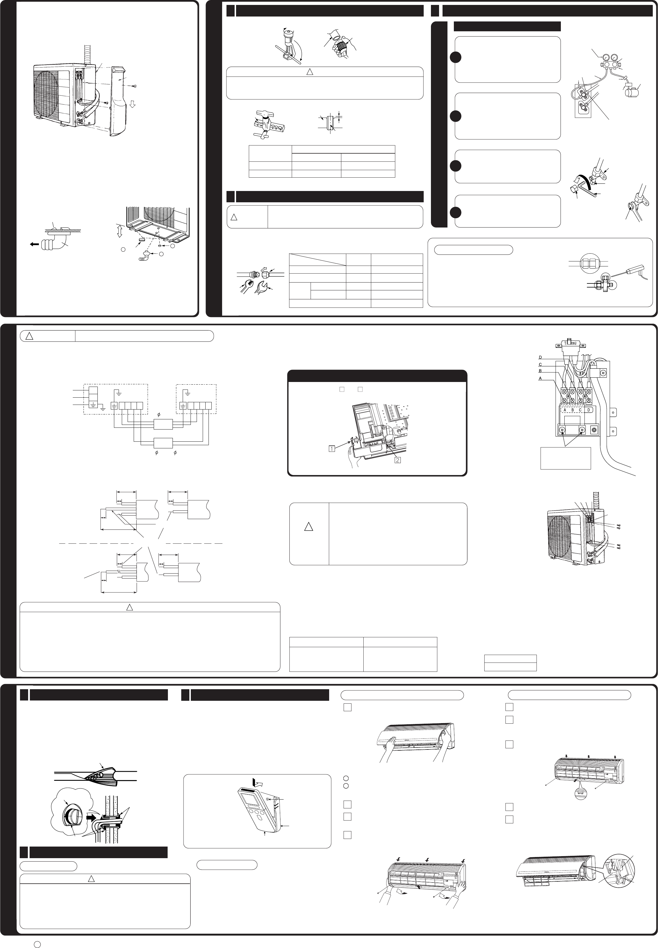
FINAL STAGE OF INSTALLATION
Insulation And Maintenance Of Pipe Connection
1
●
The connected terminals should be completely sealed with
heat insulator and then tied up with rubber strap.
●
Please tie the pipe and power line together with vinyl tape as
shown in the figure showing the installation of Indoor and
Outdoor units. Then fix their position with holders.
●
To enchance the heat insulation and to prevent water
condensation, please cover the outdoor part of the drain hose
and pipe with insulation pipe.
●
Completely seal any gap with putty.
Installation Of Remote Controller
2
Power Source And Operation Test
3
●
The remote controller can be placed in its holder which is
fixed on wall or beam.
●
To operate the remote controller at its holder, please ensure
that the unit can receive signal transmitted from the controller
at the place where the holder is to be fixed. The unit will beep
when signal is received from the remote controller. The signal
transmission is weaken by the fluorescent light. Therefore,
during the installation of the remote control holder, please
switch on the light, even during day time, to determine the
mounting location of the holder.
Power Source
CAUTION
!
●
Please use a new socket. Accident may occur due to the use of old
socket because of poor contact.
●
Please plug in and then remove the plug for 2 – 3 times. This is to
ensure that the plug is completely plugged into the socket.
●
Keep additional length for the power cord and do not render the
plug under external force as this may cause poor contact.
●
Do not fix the power cord with U-shape nail.
Operation Test
●
Please ensure that the air conditioner is in normal
operating condition during the operation test.
●
Explain to your customer the proper operation
procedures as described in the user’s manual.
<
I909: A
>
The controller must
be hooked onto the
hook at the lower
part of the holder.
Push in the remote
controller in the
direction as shown
in figure below.
3
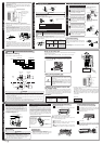
Procedures of using Vacuum Pump for Air Removal
As shown in right figure, remove the cap
of valve core. Then, connect the charge
hose. Remove the cap of valve head.
Connect the vacuum pump adapter to
the vacuum pump and connect the
charge hose to the adapter.
Fully tighten the “Hi” shuttle of the
manifold valve and completely unscrew
the “Lo” shuttle. Run the vacuum pump
for about 10–15 minutes, then completely
tighten the “Lo” shuttle and switch off
the vacuum pump.
2
Completely unscrew the spindle of the
service valve (at 2 places) in anti-
clockwise direction to allow the flow of
coolant (using Hexagonal Wrench key).
3
Remove the charge hose and tighten the
cap of valve head. Check the cap’s
periphery if there is any gas leakage.
The task is then completed.
4
1
Preparation of Pipe
1
●
Use a pipe cutter to cut the copper pipe.
●
Jagged edge will cause leakage.
●
Point the side to be trimmed downwards during trimming to prevent copper
chips from entering the pipe.
●
Before flaring, please put on the flare nut.
Pipe Connection
2
INSTALLATION OF REFRIGERATING PIPES AND AIR REMOVAL
CAUTION
!
AIR REMOVAL
WARNING
●
If you cannot attach the side cover due to the connecting
cord, press the connecting cord in direction to the front
panel to fix it.
●
Be sure that the hooks of the side cover is fixed in
certainly. Otherwise water leakage may occur and this
causes short circuit or faults.
●
The connecting cord should not touch to service valve
and pipes. (It becomes high temperature in heating
operation.)
●
The naked part of the wire core should be 10 mm and fix it to the terminal tightly. Then try to pull the
individual wire to check if the contact is tight. Improper insertion may burn the terminal.
●
Be sure to use only power cables approved from the authorities in your country. For example in Germany:
Cable type: NYM 3x1.5mm
2
.
●
Please refer to the installation manual for wire connection to the terminals of the units. The cabling must
meet the standards of electrical installation.
●
There is an AC voltage drop between the L and N terminals if power is on. Therefore, before servicing,
be sure to remove the plug from the AC outlet or switch off the main switch.
Checking for the electric source and
the voltage range
●
Before installation, the power source must be checked and necessary
wiring work must be completed. To make the wiring capacity proper, use
the wire gauges list below for the lead-in from a pole transformer and for
the wiring from a switch board of fuse box to the main switch and outdoor
unit in consideration of the locked rotor current.
●
Investigate the power supply capacity and other electrical conditions at
the installation location.
Depending on the model of room air conditioner to be installed, request
the customer to make arrangements for the necessary electrical work
etc.
The electrical work includes the wiring work up the outdoor. In localities
where electrical conditions are poor, use of a voltage regulation is
recommended.
IMPORTANT
Cable length
up to 16m
up to 15m
up to 25m
Wire cross-section
1.6mm
2
2.5mm
2
4.0mm
2
IMPORTANT
●
THIS APPLIANCE MUST BE EARTHED.
Procedures of Wiring
Wiring of The Outdoor Unit
●
Please remove the side cover for wire connection.
!
WARNING
!
CONNECTION OF POWER CORD
●
Please be careful when bending the copper pipe.
●
Screw in manually while adjusting the center. After that, use of torque wrench to
tighten the connection.
WARNING
!
In case that power is supplied from Indoor Unit
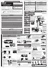
Please face this side (suction
side) of the unit to the wall.
Please remove side cover
when connecting the piping
and connecting cord.
Pull downward
BASE
DRAIN PIPE
●
Please use exclusive
tool
CAUTION
!
In case of removing flare nut of an Indoor unit, first remove a nut
of small diameter side, or a seal cap of big diameter side will fly
out. Prevent water from entering into the piping when working.
When the meter reaches - 101KPa
(-76cmHg) during pumping, fully
tighten the shuttle.
Meter showing pressure
Closed
R410A
Manifold valve
Vacuum
pump
Valve
Charge hose
Valve
Vacuum pump
adapter
When pumping starts, slightly loosen the
flare nut to check of air sucked in. Then
tighten the flare nut.
Power line Control line
Indoor
Unit
Outdoor
Unit
GRN + YEL
GRN + YEL
Strip wires
Fuse Capacity
15A time delay fuse
Earth terminal
B
A
CD
CONDENSED WATER DISPOSAL OF OUTDOOR UNIT
There are holes on the base of Outdoor unit for condensed
water to exhaust.
In order to flow condensed water to the drain, the unit is installed on a
stand or a block so that the unit is 100mm above the ground as shown
figure. Join the drain pipe to one hole.
At first insert one portion of the hook to the base (Portion A), then pull the
drain pipe in the direction shown by the arrow while inserting the hook
into the base. After installation, check whether the drain pipe cling to the
base firmly.
When using in cold region, etc.
In cold region with severe cold climate and heavy snow, water
discharged from heat exchanger freeze on the base surface and this
may affect drainage. In such a region, remove bush on the bottom face
of outdoor unit for better drainage. When using drainpipe, consult our
dealer.
A
Copper pipe
Trimming tool
A
Die
Die
Copper pipe
Wrench
Torque
wrench
Flare nut
Lo Hi
The body of
service valve
Cap of
valve core
Hexagonal
Wrench Key
Cap of valve head
Cap of valve head
L
N
DCBADCBA
Indoor Unit
Line Cord
AC 220-240V
Outdoor Unit
Connecting Cord
1.6 or 2.0
2.0
25mm
25mm
10mm
30mm
10mm
30mm
10mm
10mm
70mm
10mm
10mm
35mm
Sleeve of
protection pipe
Putty
Putty
Insulation material for pipe connection
Remote
Controller
Holder for
Remote Controller
Screw (2 pieces)
DRAIN PIPE
BUSH
100 mm ABOVE
10
9
BUSH
11
Outer
Diameter (mm)
6.35
9.52
For R410A tool
0.0
~
0.5mm
0.0
~
0.5mm
For R22 tool
A (mm)
1.0mm
1.0mm
Outer
dia.of pipe
6.35 (1/4")
9.52 (3/8")
6.35 (1/4")
9.52 (3/8")
Valve
head cap
Torque N·m
(kgf
·
cm)
13.7 – 18.6 (140 – 190)
34.3 – 44.1 (350 – 450)
19.6 – 24.5 (200 ~ 250)
19.6 – 24.5 (200 ~ 250)
12.3 – 15.7 (125 ~ 160)
Small dia. side
Large dia. side
Valve core cap
Small dia. side
Large dia. side
Method to remove the low cover
●
Pull the cover at and in the directions as shown by arrows to
remove the cover.
After remove the screw
and cover, and put the
connecting cords and fix
the cover with screw.
How to Remove The Front Cover
1 Remove the front panel.
●
Please remove and attach the front panel by both hands.
●
After opening the front panel by both hands.
Undo the right arm while pushing it inside.
Slide the front panel to right as shown in figure. Then
remove while pulling it to front.
2 Remove the filters.
3 After removing two screws, pull the center of the front
cover towards you and release the claws.
4 Pull the side faces (lower sections) of the front cover
towards you as shown in the figure and remove the
cover.
How to Attach the Front Cover
1 Check that the drain pan is securely attached.
2 After installing the front cover onto the unit, hook three
claws at upper side of the cover securely. Then, push the
center of the front cover to lock the claws.
3 Tighten the two screws.
4 Install the filter.
5 Slide the shafts of the right and left arms on the washable
panel along the steps to insert the shafts into the holes till
they stop. After checking that the shafts are securely
inserted, close the panel.
Step
Shaft
Hole
Wiring Of The Indoor Unit
●
For wire connection of the Indoor unit, you need to remove low cover and front cover.
Method to remove front cover.
●
Refer to “FINAL STAGE OF INSTALLATION – How to Remove The Front Cover”.