


7
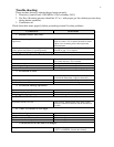
It is advisable to run a separate gas line from the meter to the gas burner to avoid pressure
drops. Refer to the above Pipe Capacity table for the correct sizes.
ALL PIPING MUST
CONFORM TO LOCAL CODES.
Use black steel pipe and malleable fittings (
do not use
cast iron parts
) with a suitable pipe dope that is resistant to liquefied petroleum gases. Test for
gas leaks using an approved gas leak tester.
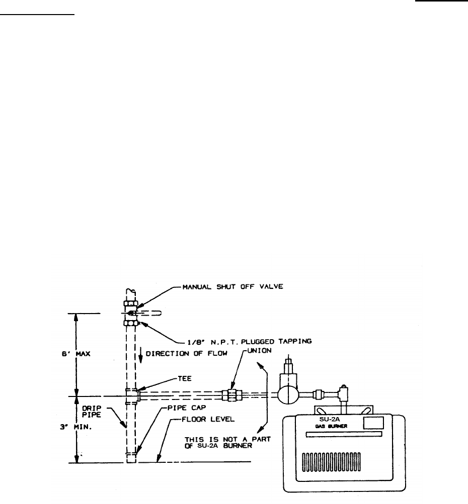
Piping should consist of:
1. A shut off valve approximately 6’ away from the unit.
2. A 1/8” plugged NPT tapping for gas pressure measurement preferably on the manual shut off
valve (as shown or anywhere between the gas valve and the shut off value).
Note: The manual shut-off valve and tapping are NOT part of the SU-2A Gas Burner.
Please make sure you conform to local and state codes.
3. A gas union.
4. A drip pipe.
Caution: The gas valve should not be subjected to more than ½” PSIG. Therefore, the
burner should be isolated during high-pressure gas leak tests.
The appliance and its
individual shut off valve must be disconnected from the gas supply piping system during any
pressure testing of that system at test pressures in excess of ½ psig. The appliance must be
isolated from the gas supply piping by closing its individual manual shut off valve during any
pressure testing of the gas supply piping system at test pressures equal to or less than ½ psig.
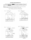
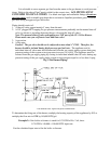
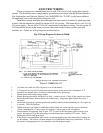
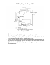
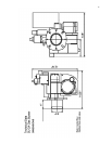
Fig. 3 Gas Burner Piping*
*The dotted lines represent field installation.
To determine the firing rate of the burner, multiply the heating capacity of the appliance by
1.2
, or
multiply the flow rate in GPH by 140,000 BTU/gal.
Example 2:
if the boiler or furnace is rated for 0.75 GPH of No. 2 oil, then:
0.75 GPH x 140,000 = 105,000 BTU input rate.
Use the calculated input rate to fire the boiler or furnace.