


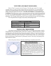
5
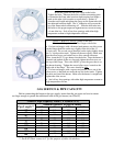
VENT PIPE AND DRAFT HOOD SIZES
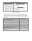
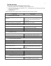
Refer to Chart 3 to properly size the flue pipe. If the flue pipe exceeds 10’ in length
(including elbows), use the next larger diameter flue pipe and draft hood. If a draft regulator is
required, any Canadian Standards Association (CSA) or Underwriter’s Laboratory (UL) listed
double swing draft regulator must be used.
A movable internal damper is not permitted on gas
installations.
When the burner is used as a conversion burner, draft over fire should be maintained
as –0.02” W.C. by adjusting the regulator when the burner is fired. The installer should follow the
barometric draft regulator manufacturer’s instructions for complete details for installations and
adjustments. The vent pipe should extend only to (but not beyond) the inside wall of the chimney.
The sizing below does not apply on any factory listed packaged units.
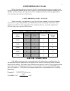
Chart 3: Vent Pipe Sizing
Input per Hour
Draft Hood and Flue Pipe Sizes
Up to 120,000 BTU
5” diameter
120,000 to 160,000 BTU
6” diameter
160,000 to 250,000 BTU
7” diameter
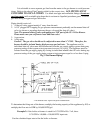
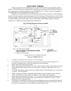
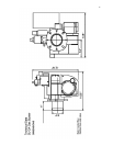
INSTALLING THE BURNER
If the burner being installed is a conversion burner, use a prefabricated chamber or build a
firing chamber that can withstand 2000
o
F (See Chart 2 on page 3). Measure the boiler or furnace
mounting plate to determine the flame tube insertion required. Deduct ¼” from the total length
and tighten the flange on the flame tube with the deducted insertion depth. The ¼” deduction will
prevent the tip of the flame tube from burning off. Install the burner on the unit and then tighten
the nuts on the flange so that the burner is permanently secured. Seal off any free openings with
high temperature cement.
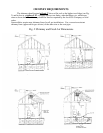
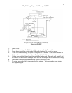
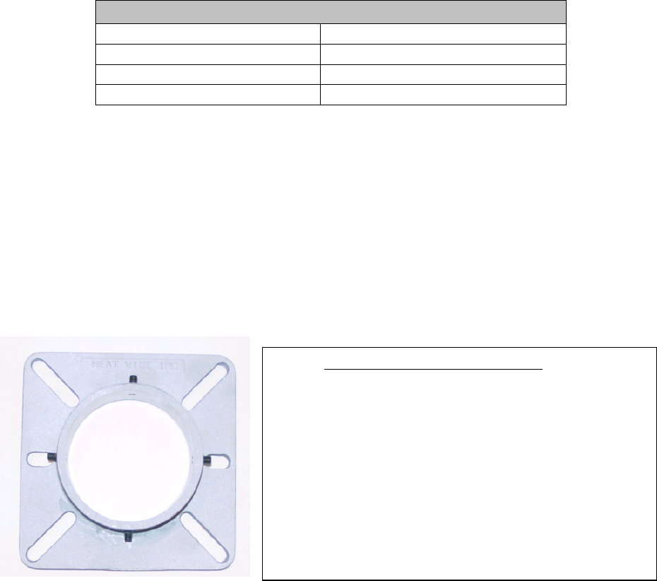
Refer to the pictures below to determine which flange is installed on the SU-2A
Picture 1: STANDARD FLANGE:
Install the gasket and the Standard flange to the
boiler. Tighten the bolts. Measure the boiler or furnace-
mounting plate to determine the flame tube insertion depth
required and make a mark on the tube (with a marker or
screwdriver). Deduct ¼” from the total length and tighten
the flange on the flame tube with the deducted insertion
depth. The ¼” deduction will prevent the tip of the flame
tube from burning off. Slide the blast tube into the boiler to
the proper depth and tighten the four ¼”-
20 setscrews. Seal
off any free openings with either high temperature cement
or high temperature silicone.