


10
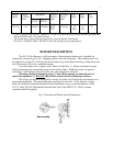
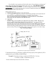
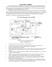
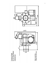
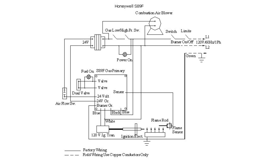
Fig. 5 Wiring Diagram for Honeywell S89F
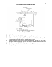
SEQUENCE OF OPERATIONS
Honeywell S89F
1. Limits close.
2. Blower motor starts as the 24 Volt transformer powers the airflow switch.
3. Power from the airflow switch to the S89F control initiates 34 second pre-purge.
4. At the end of the pre-purge, the spark is energized for 4 seconds. At the same time, the 24
Volt transformer powers the gas valve, allowing the fuel to flow.
5. Within 4 seconds, the flame should be established and proved. The spark will shut off and
the control will hold power to the gas valve until the limits open and the burner stops firing.
6. If the flame is not established, the blower motor continuously runs.
7. To restart, power should be interrupted for five minutes. Then turn on the power to start
this sequence again.