


1
1.0 INTRODUCTION
The GFK-160A Blower has been designed to circulate room
air through the fireplace to enhance heat output. The GFK160A
blower system operates on 120 VAC, 60 Hz power. This is
available through a receptacle in the factory installed junc-
tion box. The junction box is located in the controls com-
partment of the fireplace.
A variable speed control is provided with the blower system
to provide quiet forced air flow at the desired speeds. A tem-
perature sensor switch, which automatically turns the blower
ON/OFF, is also provided with this kit.
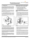
2.0 CHECK CONTENTS OF SHIPPING CARTON
Compare CONTENTS OF CARTON in Figure 1 with the ac-
tual parts received. If any parts are missing or damaged,
contact your dealer before starting installation. Do not in-
stall a damaged blower kit.
107-981K 5/03
FIGURE 1
SPEED
CONTROL
TEMP.
SENSOR
SWITCH
WING
NUT
CONTROL
NUT
BLOWER
CONTROL
KNOB
GROUND
CLIP
Printed in U.S.A. Copyright 2003
Hearth & Home Technologies Inc., 20802 Kensington Blvd., Lakeville, MN 55044
GFK-160A Blower System
- Installation and Operating Instructions -
3.0 INSTALLATION PRECAUTIONS
The GFK-160A Blower Kit is tested and safe when installed
in accordance with this installation manual. It is your respon-
sibility to read all instructions before starting installation and
to follow these instructions carefully during installation to as-
sure maximum benefit from, and safe operation of, the blower.
This blower is carefully engineered and must be installed
only as specified. If you modify it or any of its components,
you may cause a fire hazard and will void the WARRANTY.
In addition, such action may void the coverage provided by
the owner's home insurance.
CAUTION: All wiring should be done by a qualified electri-
cian and shall be in compliance with local codes and with
the National Electric Code ANSI/NFPA NO. 70-current (in
the United States), or with the current CSA C22.1 Canadian
Electric Code (in Canada).
WARNING: DO NOT CONNECT 110-120 VAC WIRING TO
THE GAS CONTROL VALVE OF THIS FIREPLACE.
4.0 INSTALLATION INSTRUCTIONS
4.1 INSTALLING ELECTRICAL SERVICE
TO THE JUNCTION BOX
WARNING: TURN ELECTRICAL POWER OFF AT THE
CIRCUIT BREAKER BEFORE BEGINNING THIS INSTAL-
LATION.
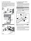
1. Remove the electrical cover plate from the lower exterior
of the fireplace. Remove the knock-out from the plate
and attach the Romex clamp (screws to the outside).
(See Figure 2). NOTE: Some fireplace models have a
round hole through which the service wires are fed and
into which the Romex clamp is attached. These models
do not have a cover plate.
FIGURE 2
LOWER
GRILLE
COVER
PLATE
110-120 VAC
2. Feed the 110-120 VAC electrical service wires through
the Romex clamp and secure the wires to the clamp.
Reattach the cover plate to the outside of the fireplace.
3. Access the controls compartment of the fireplace to lo-
cate the Junction Box.
4. Using the wire nuts, attach the black wire to the black ser-
vice wire, the white wire to the white service wire, and the
service ground wire to the ground stud of the junction box.
5. Attach the junction box to the side of the unit. Insert the
rear tab of the box into the rectangular slot in the outer
wrap of the firebox. Push the front end of the box tightly
against the side of the unit, and secure the box with a
sheet metal screw (note the hole in the front end tab).