


Note: Performance of this tool (if powered by line voltage) may vary depending on
variations in local line voltage. Extension cord usage may also affect tool perfor-
mance.
Warning: The warnings, cautions, and instructions discussed in this instruc-
tion manual cannot cover all possible conditions and situations that may oc-
cur. It must be understood by the operator that common sense and caution
are factors which cannot be built into this product, but must be supplied by
the operator.
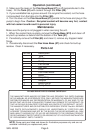
Unpacking
When unpacking, check to make sure parts listed on page 5 are included. If any
parts are missing or broken, please call Harbor Freight Tools at the number on
the cover of this manual.
SKU 45333 Page 4
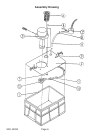
Refer to the Assembly Drawing on page 6.
1. Unsnap both of the Snap Rings (#9) and remove the Cover (#2).
2. Insert the Pump (#3) through the hole in the Cover (#2) making sure the gasket
is centered on the brim of the Pump (#3) and snug between the
Pump (#3) and the top of the Cover (#2). Put the matching metal brim (provided)
on the bottom of the Pump (#3) and snug it up to the bottom of the Cover (#2).
Line up the holes of the brim of the Pump (#3), the Cover (#2), the gasket, and
provided metal brim. Secure through the top with 3 Pan Screws (#4) and Hex
Nuts (#5).
3. Connect the Hose (#8) to the Adaptor (#10) by slipping a Hose Clamp (#11)
over the Hose (#8) and then slide the Hose (#8) onto the barbed end of the
Adaptor (#10). Tighten with Hose Clamp (#11).
4. Attach the Adaptor (#10) to the Pump Base (#12) by sliding it on (pressure fit).
5. Before snapping on the Cover (#2), insert the other end of the hose through the
smallest hole on the cover and secure it to the barbed end of the Flex
Hose Base (#7) with a Hose Clamp (#11).
6. Snap the entire Cover (#2) unit back onto the Tank (#1). Set the
Filter (#6) into the remaining hole on the Cover (#2).
1. Make sure the magnetic Flex Hose Base (#7) is near your workpiece and the
magnetic base is secure to the metal table you are working on. The tip of the
Hose (#8) on the Flex Hose Base (#7) should be almost contacting the
workpiece.
Assembly
Operation
Warning! Position the electrical cord and plug so that it is not in contact with
coolant or wet surfaces.
REV 09/03