


OPERATING INSTRUCTIONS
NOTE:All parts mentioned below refer to parts shown on the reverse side of this
instruction sheet.
Fold
Fold
3491 Mission Oaks Blvd., Camarillo, CA 93011
Visit our Web site at http://www.harborfreight.com
Copyright © 2000 by Harbor Freight Tools. All rights reserved. No portion of this manual or any artwork
contained herein may be reproduced in any shape or form without the express
written consent of Harbor Freight Tools.
For technical questions please call 1-800-444-3353
Model 43242
MINI AIR FILTER
UNPACKING
When unpacking, check to make sure all parts shown on the back of this instruction
sheet are included. If any parts are missing or broken, please call Harbor Freight Tools
at the number shown on the front of this instruction sheet as soon as possible.
SEE REVERSE SIDE OF THIS INSTRUCTION FLYER FOR PRODUCT
WARNINGS, PRECAUTIONS, PARTS LIST, AND ASSEMBLY DIAGRAM.
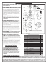
1. For ease of use, and to avoid damage to the Mini Air Filter, it is recommended that the unit be
mounted in a convenient location on the workbench or in the work area. This can be done by
attaching the Mounting Bracket (part #22) to the side of the workbench or wall, using two
wood or metal screws (not provided). (Figure A)
2. Once the Mounting Bracket has been attached to a desired location, unscrew and remove the
Retaining Ring (part #23) from the top of the Mini Air Filter.
3. Insert the top of the Mini Air Filter through the Mounting Bracket and secure by replacing the
Retaining Ring.
4. Attach a 1/4” NPT Female hose connector to the air compressor supply hose. Then, wrap the
threads of the 1/4” NPT Female hose connector with approximately 3” of Teflon tape. Next,
connect the 1/4” NPT Female hose connector to the inlet side of the Mini Air Filter.
5. Attach a 1/4” NPT Male hose connector to one end of the outlet extension hose (to which you
will connect a tool). Check to make sure the other end of the outlet extension hose is fitted
with a quick coupler. Then, wrap the threads of the 1/4” NPT Male hose connector with
approximately 3” of Teflon tape. Next, connect the 1/4” NPT Male hose connector to the outlet
side of the Mini Air Filter.
6. Connect the quick coupler of the air outlet extension hose to the tool you are using. Turn on
the air compressor and regulate the desired PSI to the tool by pulling up and turning the
Pressure Adjustment Knob (part #1) on the Mini Air Filter clockwise for reduced air pressure,
or counterclockwise for increased air pressure. Press down on the knob to lock.
7. The Mini Air Filter is now ready for use. NOTE: Depending on usage, periodically examine
the Drain Cup (part #11) for accumulated water that is being separated from the compressed
air system. See Step one for instructions on draining the excess fluid from the Drain Cup.
CLEANING AND MAINTENANCE
1. When the water level rises to the bottom edge of the
Filter Mesh Mounting (part #9) within the Drain Cup (part
#11) it is necessary to remove the excess fluid. To drain
the fluid slowly turn the Water Valve Drain (part #14)
counterclockwise until the fluid begins to flow from the
Drain Cup. When all of the fluid has been drained turn
the Water Valve Drain clockwise to tighten.
2. To clean, wipe with a clean, damp cloth, using a mild
soap with water if necessary. Then, dry.
FIGURE A
22
AIR OUT-
LET
11
9
14
1
23
With Pressure Gauge and Pressure Regulator
REV 01d; 07g