Installation
Flange Connec
tions
The fluid inlet and outlet ports are 2 in. (50 mm)
raised face, ANSI/DIN PN 10 flanges. Connect 2 in.
(50 mm) plastic pipe flange to the pump as follows.
You will need:
• Torque wrenc
h
• Adjustable w
rench
• 6 in. (152 mm
) diameter, 1/8 in (32 mm) thick
PTFE gasket
,withfour0.75in(19mm).diameter
holes on a 4.
75 in. (121 mmm) diameter bolt circle,
anda2in.(
50 mm) diameter center
• Four 5/8 in
(17 mm) x 3 in (76 mm) long bolts
• Four 5/8 in
.(17 mm) spring lock washers
• Eight 5/8 i
n. (17 mm) flat washers
• Four 5/8 i
n. (17 mm) nuts
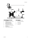
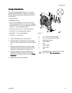
1. Place a flat washer (K) on each bolt (H).
2. Align the holes in the gasket (G) and the pipe
flange (F) with the holes in the pump outlet flange
(E).
3. Lubricate the threads of the four bolts. Install
the bolts through the holes and secure with the
washers (K), lock washers (J), and nuts (L).
4. Holdthenutswithawrench. Refertothe
tightening sequence in the figure and torque
theboltsto20to30ft-lb(27to41Nm).Do not
overtorque.
5. Repeat for the pump inlet flange.
Figure 1
D
2 in. (50 mm) fluid inlet flange
E
2 in. (50 mm) fluid outlet flange
F
Plastic pipe flange
G
PTFE gasket
HBolt
J Lock washer
K Flat washer
LNut
Lubricate threads. torque to 20 to 30 ft-lb
(27to41Nm).Do not overtorque.
3A2578B 13


