


22618-4-1106Page 22
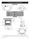
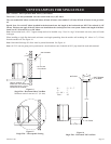
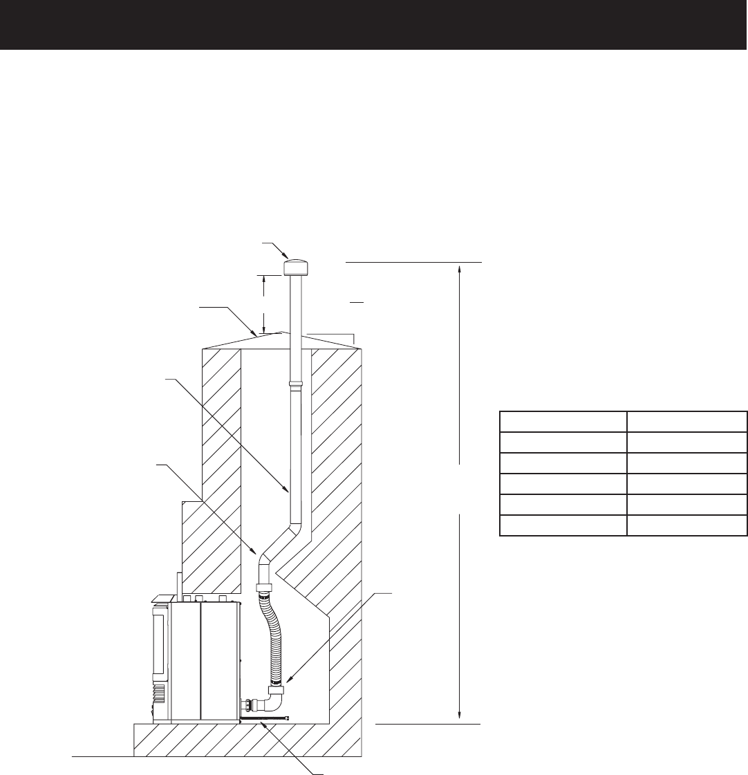
VENT EXAMPLES FOR SINGLE FLUE (cont.)
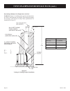
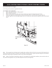
FLEXIBLE
FLUE KIT
FLEXIBLE GAS
LINE
PVC PIPE SWV
(SUPPLIED BY INSTALLER)
(2) - 45 DEG. PVC BENDS
(SUPPLIED BY INSTALLER
IF NECCESSARY)
GALV. SHEET FLASHING
TO SEAL CHIMNEY
(SUPPLIED BY INSTALLER)
VENT CAP (SUPPLIED
WITH VENT KIT)
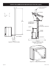
H
12
X
ROOF PITCH
IS
12
X
17’
5.2m
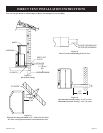
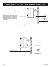
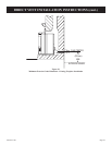
Figure 22
Venting for Existing Fireplace Installation
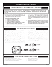
Determining Minimum Vent Height Above the Roof
WARNING: Major U.S. building codes specify minimum chim
-
ney and/or vent height above the rooftop. These minimum heights
are necessary in the interest of safety. These specifications are
summarized in Figure 22.
90° = 3’
V = 17’
Total = 20’
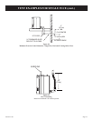
ROOF PITCH H (Min.)
Flat to 6/12 12” (305mm)
6/12 to 7/12 15” (381mm)
Over 7/12 to 8/12 18” (457mm)
Over 8/12 to 16/12 24” (610mm)
Over 16/12 to 21/12 36” (914mm)