


19
LIMIT SWITCH / FORCE ADJUSTMENT
FOR HELP-1.800.354.3643 OR GENIECOMPANY.COM
6
NOTE: During operator cycling for force
adjustment, the motor protector may shut off
power to the operator. If this occurs, wait about
20 minutes to allow the motor protector to reset.
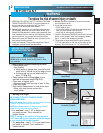
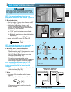
1. Adjusting limit switches.
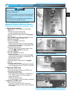
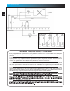
• Locate force control knobs on power head
(Fig. 7-1).
– Gently turn both control knobs
counter-clockwise until they stop.
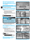
• Verify emergency release lever in disengaged
position.
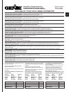
• Verify “OPEN” limit switch at point where chain
attaches to carriage slide
(Fig. 7-2).
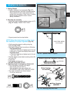
• Manually close door.
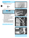
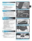
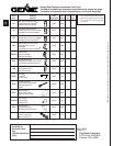
• Move the “CLOSE” limit switch:
– Loosen set screw.
–
Slide limit switch along rail to align front edge
of switch with back edge of carriage (Fig. 7-3).
– Gently tighten set screw.
• Press wall control button.
– Carriage slide will move toward power head
and stop at the “OPEN” limit switch.
• Manually open door.
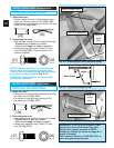
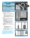
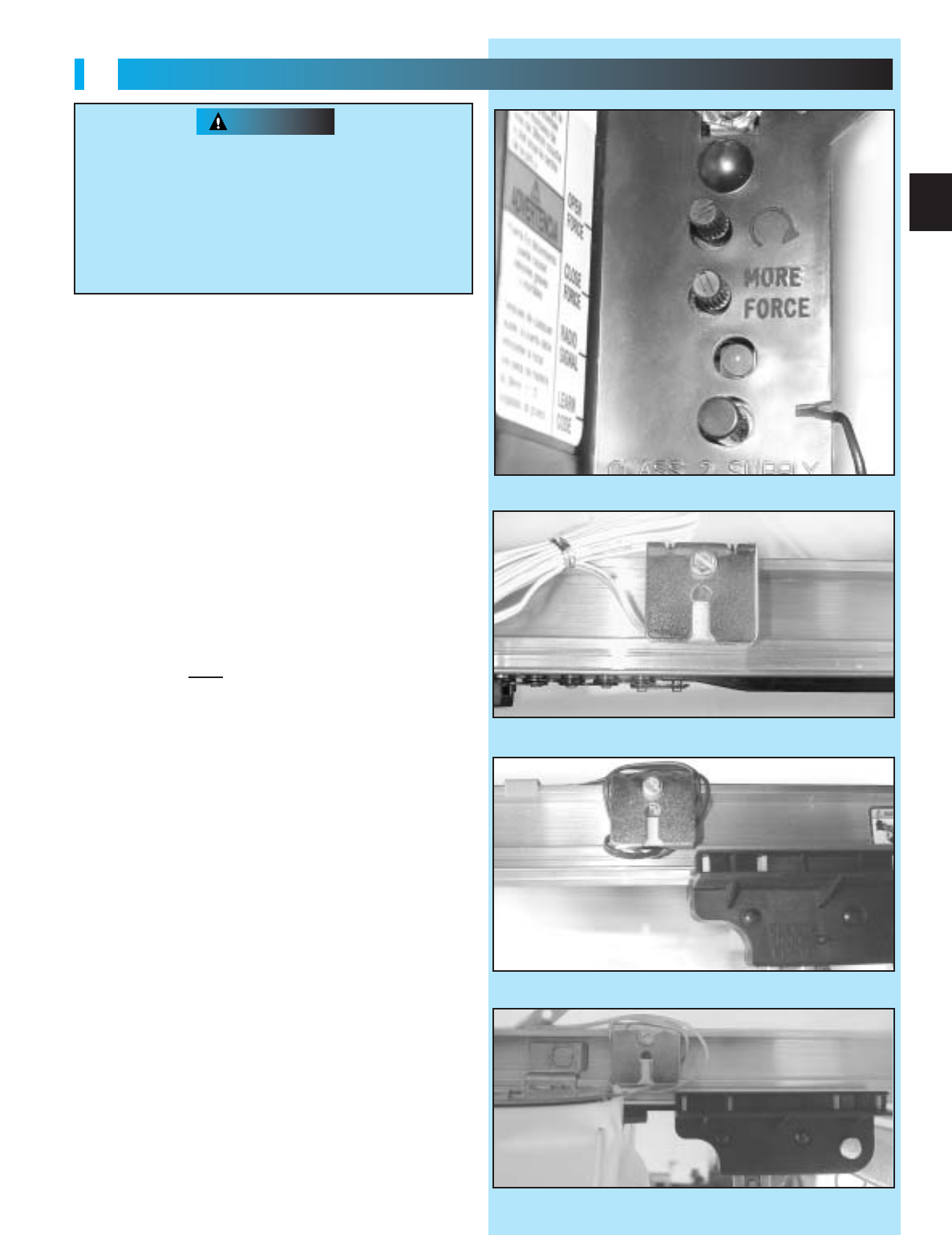
• Move the “OPEN” limit switch:
– Loosen set screw.
–
Slide limit switch along rail to align front edge
of switch with back edge of carriage (Fig. 7-4).
– Gently tighten set screw.
– Manually close door.
• Place emergency release lever in engaged
position.
• Press wall control button.
– Carriage slide will move toward door, engage
with carriage and stop at “CLOSE” limit switch.
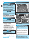
2. Adjusting “OPEN” force.
• Press wall control button.
–
Door should open and stop at “OPEN” limit.
• Door does not fully open.
– Press wall control button.
– Door should close and stop at “CLOSE” limit.
– Turn
“OPEN”
force control knob slightly in
clockwise direction.
– Press wall control button.
a. Continue step 2 until door opens completely.
3. Adjusting “CLOSE” force.
• Door is not fully closing.
– Cycle door, turning “CLOSE” force knob
clockwise slightly each time until door reaches
fully closed.
DOOR OPENS RAPIDLY
.
Keep the path clear
.
Position the ladder to the side of the power head
so it is clear of all moving parts of the operator
and door.
Always set the door operator to the minimum
force required to operate the door
.
WARNING
FIG. 7-1 Force adjustment screws.
FIG. 7-3 Align “CLOSE” limit switch.
FIG. 7-4 Align “OPEN” limit switch.
FIG. 7-2 Place “Open” limit switch.