


18
CONNECTING TO POWER
FOR HELP-1.800.354.3643 OR GENIECOMPANY.COM
5
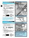
1. Plug the operator into a properly grounded
electrical outlet.
2. Check Safe-T-Beam
®
alignment (Fig. 6-3).
To reduce the risk of electrical shock, this
equipment has a grounded type plug that includes
a third (grounding) pin. This plug will only fit a
grounded type outlet. If you do not have a
grounded outlet, contact a qualified electrician to
install one. DO NOT alter the plug in any way. The
door operator must be properly grounded in order
to prevent personal injury and damage to
the components.
WARNING
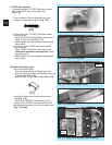
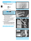
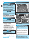
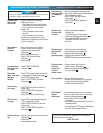
FIG. 6-1 Removing motor cover.
Check local building codes to make sure that you
are not required to have your garage door operator
permanently wired, with circuit breaker protection.
If permanent wiring is required, have this installed
by a qualified electrician.
CAUTION
1. Instructions for electrician.
• Remove power from circuit.
• Remove motor cover (Fig. 6-1)
.
– Removing hex head screw located in center
on bottom of cover.
– Slide cover down and off.
• Remove and throw away existing power cord.
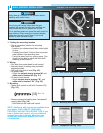
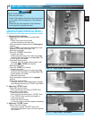
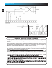
• Remove 7/8" knockout plug (Fig. 6-2).
– Install a suitable entrance bushing.
• Connect permanent wiring to power head
.
–
White to white/black to black / ground to green
.
– Use only UL recognized wire nuts.
• Wires inside power head must be at least 6"
in length.
• Replace motor cover and re-energize
the circuit.
2. Check Safe-T-Beam
®
alignment (Fig. 6-3).
The electrical power to the door operator MUST
BE turned off when the motor cover is removed.
Electrical power must remain off while making
electrical connections.
WARNING
WITH GROUNDED PLUG:
WITH PERMANENT WIRING:
The circuit board is light sensitive. Make sure
the motor cover has been replaced prior to
re-energizing the circuit.
CAUTION
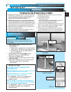
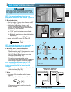
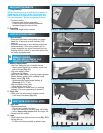
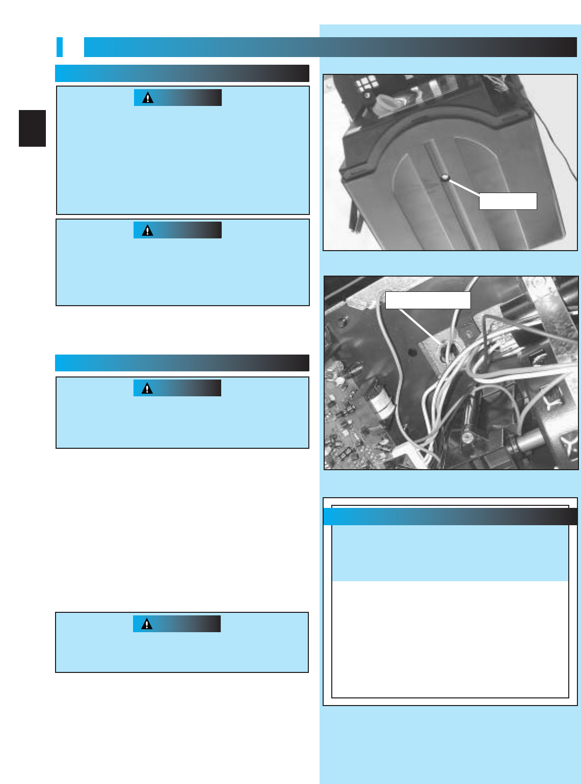
Safe-T-Beam
®
Alignment Check
FIG. 6-2 Knock-out plug.
NOTE: The Genie Company is not responsible
for charges resulting from work performed by an
independent electrician.
FIG. 6-3
screw
knock-out plug
After turning the electrical power on, if the
STB’s are not in proper alignment, the red
LED (Source) will blink continuously.
To correct the problem — the brackets are
flexible and can be adjusted slightly to bring
the system into alignment.
When the STB’s are in alignment the red
LED will stop blinking and stay on.
NOTE: If a problem exists with the “STB” that is
preventing the door from closing, the door can be
closed by holding the wall control button in until the
door is fully closed. (The remote control will not work.)