


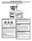
Installation Instructions
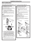
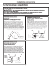
FEED WATER SUPPLY (cont.)
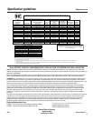
C. OPTIONAL INSTALLATION 2
Where codes permit (Requires additional parts)
*For 1/2” OD or larger metal tubing only.
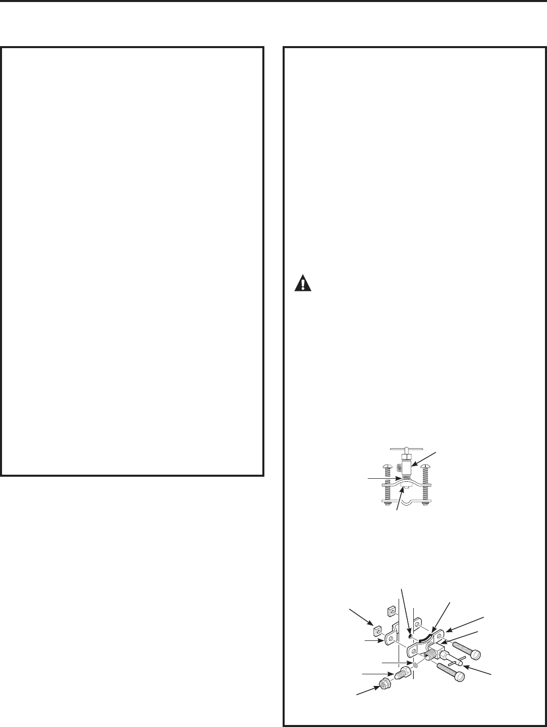
NOTE: Codes in certain states require installation
by a licensed plumber and do not permit the
use of the saddle valve. For installation, use
plumbing code 248-CMR of the Commonwealth of
Massachusetts.
Saddle valve is available through GE Parts
and Services at 1.800.626.2002, part number
WS15X10023. Self-piercing saddle valves are not
recommended.
1. Turn off the cold water supply and attach
saddle valve as required by product selection.
(Be sure to follow manufacturer’s Installation
Instructions.)
DANGER: Many homes are electrically
grounded through the plumbing. To protect
yourself from serious injury or fatal shock, use a
battery-powered hand drill only to make the hole.
DO NOT USE AN ELECTRIC DRILL.
2. Close the water supply valve by turning the
handle clockwise.
3. Open the main water supply valve and several
house faucets to purge air from the system.
Close faucets when water runs smoothly.
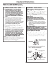
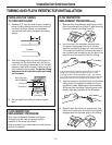
Snug valve into bracket
(DO NOT OVER TIGHTEN)
Some threads
should be visible
Optional water supply connection (using saddle valve)*
Pre-drill
1/4” hole
6HDO³PDNHVXUHWKH
seal is in place
Clamp X
1XW³QRW
required if holes
in clamp are
threaded
Valve
Handle
Tubing adapter
Washer
Compression
nut
Í
Clamp Z
8VHWRFRQQHFWWKHWXELQJ
*For 1/2” OD or larger metal tubing only.
12
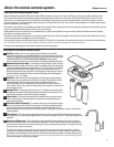
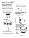
B.
OPTIONAL INSTALLATION 1 (CONT.)
4. Assemble adapter (C) and coupling (D) as
shown in illustration on page 9, per your
configuration. Ensure that the gasket (G) is in
place before final assembly. Start installation
by hand; then finish tightening with adjustable
wrench. Be careful not to over tighten or
cross-thread since damage to threads may
occur.
5. Hand-tighten assembled adapter (C) onto
supply valve (A) for the proper size installation.
Be sure gasket (G) is in place before final
assembly. Start installation by hand, then
finish tightening with an adjustable wrench. Be
careful not to over tighten or cross-thread
since damage to threads may occur.
6. Reconnect faucet tubing line (B) to top of
adapter (C).
7. Cut wire ties on tubing coils, using care not to
damage tubes or parts if using a utility knife.
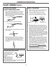
8. Remove the 1/2” nut (I) and ferrule (H) from end
RILQOHWYDOYH8VLQJWKH\HOORZEDQGHGWXELQJ
provided, place the nut (I) and ferrule (H) onto
the tubing and install onto inlet valve (F) as
shown at left. Tighten with adjustable wrench.
Be careful not to over tighten or cross-thread
since damage to threads may occur.
NOTE: Inspect the ends of the tubing prior
to installation to be sure there are no imperfections
and that the end of the tubing is cut square. It may
be necessary to cut the tubing again.
Rubber gasket