


Installation Instructions
FEED WATERSUPPLY
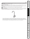
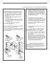
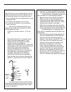
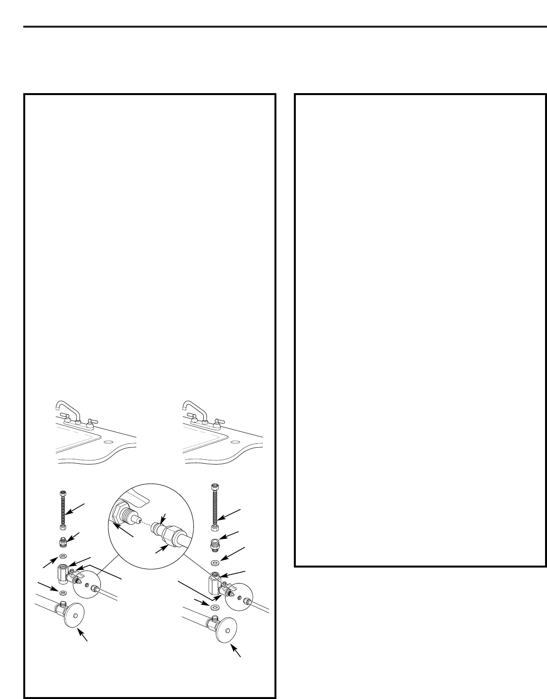
A. PREFERRED INSTALLATION
Utilizing existing kitchen sink water supply
valve (A) and removable faucet tubing (B).
1. Refer to illustration below to complete
assembly depending on supply valve
size (A).
2. Close the cold water supply valve (A)
under the sink.
3. Unscrew the flexible tubing line (B) from
the supply valve (A) that connects to the
COLD water riser.
NOTE: For rigid pipe, see C. Optional
Installation on page 10.
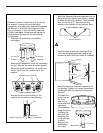
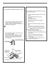
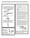
Note Adapter (C)orientation:
3/8-inch installation—Rounded end of adapter
(C) connects to supply valve (A).
1/2-inch installation—Rounded end of adapter
(C) connects to coupling (D), then to existing
faucet tubing (B).
Check and comply with local plumbing codes as you plan, then install a cold feed water supply fitting.
4. Assemble adapter (C) and coupling (D)
as shown in illustration at left, per your
configuration. Ensure that the gasket (G)
is in place before final assembly. Start
installation by hand, then finish tightening
with adjustable wrench. Be careful not
to overtighten or cross thread as damage
to threads may occur.
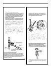
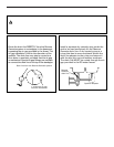
5. Hand tighten assembled adapter (C)
onto supply valve (A) for the proper size
installation. Be sure gasket (G) is in place
before final assembly. Start installation
by hand, then finish tightening with an
adjustable wrench. Be careful not to
overtighten or cross thread as damage
to threads may occur.
6. Reconnect faucet tubing line (B) to top
of adapter (C).
NOTE: If inlet valve (F) is to be removed
for installation, refer to E. Removal and
Reinstallation of Inlet Valve on page 11.
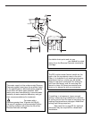
7. Cut wire ties on tubing coils, using care
not to damage tubes or parts if using a
utility knife.
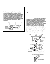
8. Remove the 1/2″ nut (I) and ferrule (H)
from end of inlet valve. Using the yellow
banded tubing provided, place the nut (I)
and ferrule (H) onto the tubing and install
onto inlet valve (F) as shown at left.
Tighten with adjustable wrench. Be
careful not to overtighten or cross thread
as damage to threads may occur.
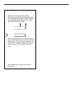
NOTE: Inspect the ends of the tubing prior
to installation to be sure there are no
imperfections and that the end of the tubing
is cut square. It may be necessary to cut
the tubing again.
9
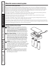
For 3/8″ Plumbing For 1/2″ Plumbing
(B) Faucet
tubing line (not
included)
(D)
Coupling
(C)
Adapter
(F) Inlet valve
(A) Cold water
supply valve
(not included)
(B) Faucet
tubing line
(not included)
(A) Cold water
supply valve
(not included)
(D)
Coupling
(C)
Adapter
(G) Gasket
(G)
Gasket
(H)
Ferrule
(F) Inlet valve
(I) Nut
(G) Gasket