


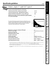
Installation Instructions
D. OPTIONAL REMOTE LOCATION
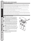
INSTALLATION
(requires additional part)
1. Turn off the cold water supply.
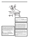
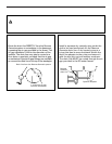
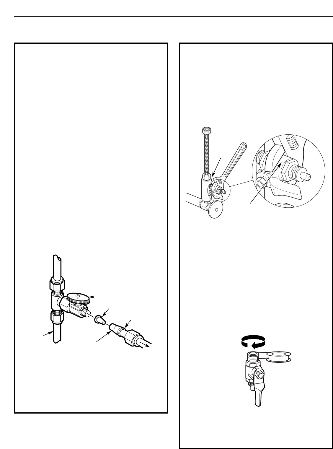
2. Complying with plumbing codes, install a
fitting on the cold water pipe to adapt 1/4″
OD tubing. A typical connection is shown
in illustration below. Make sure a water
supply valve is used.
3. If the RO unit is to be installed more than
6 feet from the valve, replace the yellow
banded inlet tubing with a longer length
of GE 1/4″ tubing. A 33 foot length of 1/4″
tubing is available through GE Parts and
Services at 1.800.626.2002, part number
WS07X10018. DO NOT SUBSTITUTE
TUBING OF UNKNOWN QUALITY.
4. If the RO unit is to be installed more than
6 feet from the faucet, replace the blue
banded outlet tubing with a longer length
of GE 3/8″ tubing. A 33 foot length is
available through GE Parts and Services at
1.800.626.2002, part number WS07X10019.
See Faucet Installation on page 13 for more
details. DO NOT SUBSTITUTE TUBING OF
UNKNOWN QUALITY.
If you are using copper tubing, DO NOT
connect it directly onto the RO unit. Purchase a
connector and use a short length of the yellow
banded tubing provided to make final connection
to RO. Do not use copper tubing to attach to
icemaker or faucet.
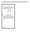
Insert (not included)
Cold
water
pipe
1/4″ (yellow banded)
tubing to inlet
Ferrule
Water supply valve
To RO
Preferred water supply connection
(using compression fitting)
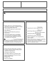
E. REMOVALANDRE-INSTALLATION
OF INLET VALVE
(required only if
inlet valve needs to be removed to
complete Step 5 on page 13)
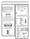
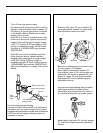
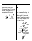
1. Remove inlet valve (F) from adapter (C)
using adjustable wrench on valve body.
See illustration below for detail. DO NOT
USEWRENCH ONHEX NUTEND OF
VALVE AS LEAK MAY OCCUR.
2. Remove all sealing tape from inlet valve
(F) and adapter (C) threads.
3. Hand tighten assembled adapter (C)
onto supply valve (A) for the proper size
installation. Be sure the gaskets (G), as
shown on page 13, are in place before
final assembly. Finish tightening with
adjustable wrench. Be careful not to
overtighten or cross thread as damage
to threads may occur.
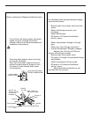
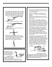
4. Using white thread sealing tape provided,
apply approximately 9 wraps of tape
around the large threads on inlet valve (F)
in a clockwise direction, as shown below.
5. Hand tighten inlet valve (F) into the adapter
(C), then finish tightening with adjustable
wrench. DO NOT USE WRENCH ON HEX
NUT END OF VALVE AS LEAK MAY OCCUR.
11
(C)
Adapter
(F) Inlet valve