


52
Zoneline
®
Chassis Nomenclature
EXAMPLE
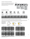
Receptacles/Sub-Bases
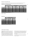
The Zoneline chassis is identified by a model number defining
the type of unit, cooling capacity, electrical information and
optional features included on the unit. When specifying or
ordering the Zoneline chassis use of this nomenclature will
assure receiving the correct unit.
AZ61H12DAD
Chassis series
41= deluxe line cool/
electric heat
61= deluxe line
heat pump
Unit type
E= cooling with electric
resistance heat
H= heat pump with electric
resistance heat
Zoneline
packaged
terminal
chassis
Nominal cooling capacity
07=7,000 BTUH cooling
09=9,000 BTUH cooling
12=12,000 BTUH cooling
15=15,000 BTUH cooling
Special Features
B=base unit
C=corrosion treated
D= internal
condensate
removal (ICR)
system (heat
pump models
only) (not for
coastal areas)
P=Dry Air 25
Voltage/Phase/
Frequency
D= 230/208 Volt, single
phase, 60 Hz
E= 265 Volt, single phase,
60 Hz
Universal
power connection
RAK204U RAK204D15P RAK204D20P RAK204D30P RAK204E15 RAK204E20 RAK204E30
Voltage N/A 230/208 230/208 230/208 265 265 265
Amps N/A 15 20 30 15 20 30
Receptacle N/A NEMA6-20R NEMA6-20R NEMA6-30R NEMA7-15R NEMA7-20R NEMA7-30R
230/208 Volt sub-bases include appropriate power cord kit.
265 Volt units are to be direct connected. Cordset through enclosed chaseway into interior sub-base receptacle meets the NEC requirements.
Sub-bases
Tandem
230/208V 15 Amp
NEMA6 -15R
Perpendicular
230/208V 20 Amp
NEMA6-20R
Large tandem
230/208V 30 Amp
NEMA6-30R
265V 15 Amp
NEMA7-15R
265V 20 Amp
NEMA7-20R;
265V 30 Amp
NEMA7-30R;
Power connection kits are required on all Zoneline
®
chassis (see chart below).
The correct kit for the installation is determined by the voltage and amperage of the electrical circuit and the means of connecting the unit to the
building wiring. If the unit is to be plugged into a receptacle, a line cord kit would be used; if the unit is to be permanently connected, a permanent
connection kit would be used. 265 volt cord set units must be installed in compliance with National Electrical Code
®
.
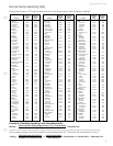
Power connection kits
Required on all models.
See specification sheet
for heater KW and branch
circuit ampacity.
RAK3153/3203/3303
230/208 volt line cord
connection kit
RAK4157/4207/4307
230/208 volt universal
power supply kit
RAK5157/5207/5307
265 volt universal power
supply kit
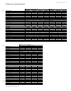
230/208 volt Line cord connected units
LCDI Power Connection Kit RAK3153* RAK3203* RAK3303*
Heater KW 2.4/2.32 3.3/3.2 4.7/4.53
Watts 2,400/2,320 3,300/3,200 4,700/4,530
BTUH 8,150/7,900 11,200/10,900 16,000/15,450
Amps 11.0/11.6 15.1/16.0 21.2/22.4
Min. circuit amps 15 20 30
Recommended
protective
device
15 amp
time delay
fuse or breaker
20 amp
time delay
fuse or breaker
30 amp
time delay
fuse or breaker
265 volt Permanent connected units** (Cord set)
RAK5172 RAK5202 RAK5302
2.4 3.4 4.8
2,400 3,400 4,800
8,150 11,550 16,350
9.6 13.3 18.6
15 20 30
15 amp
time delay fuse
20 amp
time delay fuse
30 amp
time delay fuse
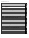
230/208 volt Direct connection kit†
RAK4157 RAK4207 RAK4307
Heater KW 2.4/2.32 3.3/3.2 4.7/4.53
Watts 2,400/2,320 3,300/3,200 4,700/4,530
BTUH 8,150/7,900 11,200/10,900 16,000/15,450
Amps 11.0/11.6 15.1/16.0 21.2/22.4
Min. circuit amps 15 20 30
Recommended
protective
device
15 amp
time delay
fuse or breaker
20 amp
time delay
fuse or breaker
30 amp
time delay
fuse or breaker
265 volt Direct connection kit†
RAK5157 RAK5207 RAK5307
2.4 3.4 4.8
2,400 3,400 4,800
8,150 11,550 16,350
9.6 13.3 18.6
15 20 30
15 amp
time delay fuse
20 amp
time delay fuse
30 amp
time delay fuse
* RAK3153, RAK3203 and RAK3303 will be transitioning to RAK3153A, RAK3203A and RAK3303A respectively. Old and new models are interchangeable, and there will be no change in performance.
**To be used with sub-base
†To be used with sub-base or connection to building wiring
Preliminary specifications subject to change.