


36
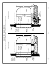
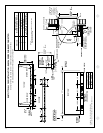
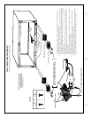
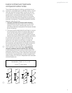
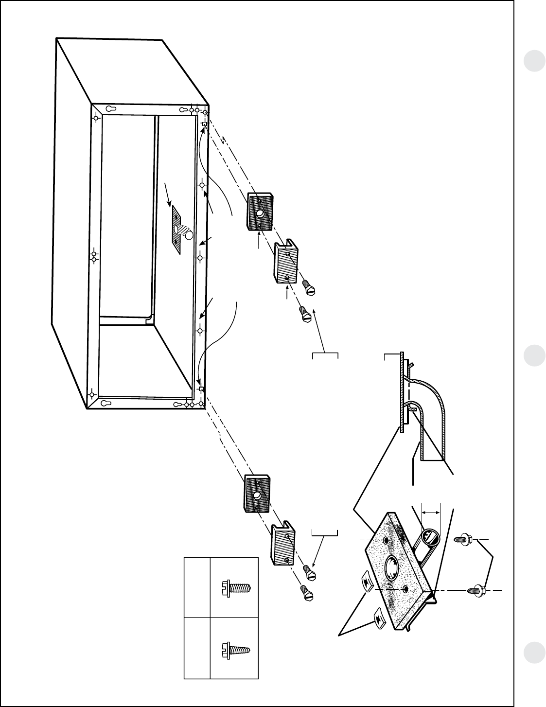
WALL CASE WITH RAD10 DRAIN KIT
Internal Drain. See page 35 for external drain.
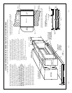
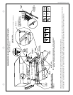
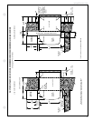
SCREWS
“A”
METAL
“B”
PLASTIC
NEOPRENE SPONGE GASKET
STEEL MOUNTING PLATE
USE TYPE “A” SCREW FOR METAL CASE (RAB71)
AND TYPE “B” SCREW FOR MOLDED CASE (RAB77)
NOTE: SHADED PARTS AND SCREWS
INCLUDED WITH RAD10 DRAIN
KIT. THE 90° ELBOW TUBE IS
RECOMMENDED FOR INTERNAL
DRAIN INSTALLATION.
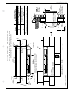
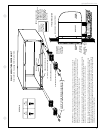
OVERFLOW RELIEF DRAIN
SEE NOTE 6
SEE DETAIL
BELOW
USE TYPE “A” SCREWS FOR BOTH RAB71A AND RAB77
NUT
(MOLDED CASE (RAB77) ONLY)
DETAIL
GASKET
CABINET BOTTOM
TUBE
1/2" OD
COVER
PLATE
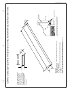
1. The RAD10 drain kit is installed in the bottom of the wall case when it is desired to drain
condensate to an internal drain system in the building.
2. The drain kit is mounted on the bottom of the wall case prior to installation of the case in the
wall. It may be located anywhere on the room-side portion except for sub-base installations.
For these the drain should be at least 3" from the indoor edge of the case so as to adequately
clear the sub-base.
3. A template is furnished with the kit for locating the necessary three holes in the case bottom
—two to provide a securing means and one to provide a drain hole for the 1/2" OD tubing
(see details at left).
4. A tube or hose 1/2" I.D. (obtained locally) must be installed on the drain tube and connected to
the internal drain system in the building.
5. With the RAD10 the two square drain holes in the bottom outer flange of the wall case are
sealed by the gaskets and mounting plates shown above.
6. Three (3) 1/2" diameter holes located 1/4" above the case bottom in the bottom outer flange
provide overflow drainage to the outdoors when wind-driven rain enters the chassis.
SQUARE DRAIN HOLES