


33
geappliances.com
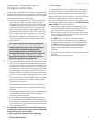
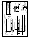
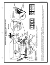
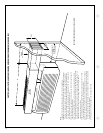
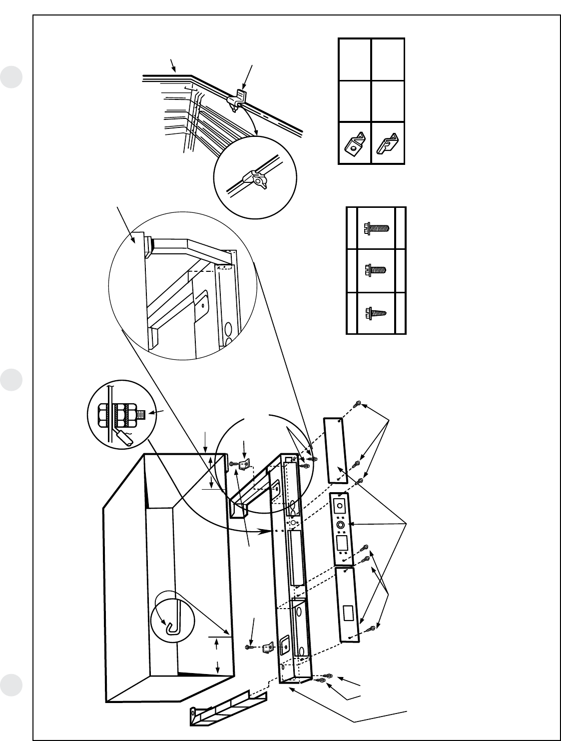
RAK204 SERIES SUB-BASE INSTALLATION AND ELECTRICAL DATA
RAB71A/77 Wall Case
RAK4002B
CHASEWAY OPTION
(Shown Without Chassis and Wall Case for Installation Location Only.)
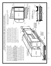
NOTE: TYPE “E”
MOUNTING CLIP MUST
BE USED WITH MOLDED
CASE.
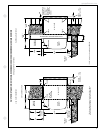
MOLDED
CASE
SUB-BASE
MOUNTING CLIP
TYPE “E”
TYPE
“D”
USE WITH
RAB71A
TYPE
“E”
USE WITH
RAB77
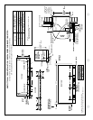
TYPE “A” TYPE “B” TYPE “C”
6 REQ’D. 2 REQ’D. 8 REQ’D.
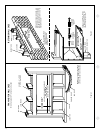
GREEN
GROUND
SCREW
(TYPE “C”)
METAL CASE
SCREW CLIP
TYPE “D”
TYPE “A”
SCREW
TO SECURE
SIDE CHANNELS
6"
5/32" DIA. HOLE (SEE NOTE)
FOR SECURING TYPE “D”
CLIPS TO SLEEVE USING
TYPE “A” SCREWS
6"
TYPE “A”
SCREW
TYPE “C”
SCREW
ACCESS PLATES
TYPE “C”
SCREW
TYPE “B” SCREW
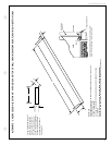
SIDE CHANNELS ARE ADJUSTABLE
FROM 13-3/4" TO 2-3/8" IN LENGTH
BY BREAKING OFF SECTIONS OF SIDE
CHANNELS.
NOTE: IF METAL CASE DOES NOT HAVE SCREW HOLES, 5/32" DIA. HOLES MUST
BE DRILLED 6" FROM EACH SIDE IN FRONT FLANGE. (SEE INSERT).
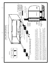
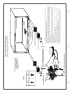
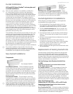
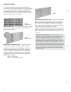
Electrical wiring may enter the sub-base through any of the knockout holes provided in the sub-base.
Knockout holes in the sub-base access plate may accommodate a receptacle, which allows the use of a power cord (if permitted by code for the particular installation).
A knockout for a circuit breaker, fuseholder or a disconnect is also provided. See pages 22 and 23 for description of electrical contents of these sub-bases.