


14
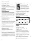
Central Desk Control
Some installations may want to govern the ability of the unit
to operate from a control device remote to the unit or even
remote to the room in which the unit is located. The general
term given to systems such as this is Central Desk Control.
The most common installation of this type of system is a
switch mounted at the registration desk and, upon guest
check-in, a button is pushed or a switch is moved to allow
the air conditioner to operate. Likewise, when the guest
checks out the device is put into the “OFF” position so the
unit will not operate while the room is vacant.
It is not necessary that the controlling device be located
at a central desk to employ a device that will control the
unit operation. For instance, in some resort areas devices
are connected to sliding glass doors and opening the door
causes a contact to close, turning the air conditioner off.
This prevents energy being wasted by operating the air
conditioner when warm, humid air is entering the room.
Some systems operate by motion sensors or heat-sensing
detectors mounted in the room. These types of systems
determine occupant presence in the room and allow the
unit to operate; if no one is in the room the device signals
the air conditioner to turn off.
Zoneline
®
models offer load-shedding capabilities on
units connected to Central Desk Control systems. For
more information on the models’ load-shedding feature,
see page 10.
There is a wide variety of devices available, each with
its own benefits and constraints. While GE does not offer
components that are external to the unit for a Central Desk
Control (CDC) system, GE Zoneline units are compatible with
most CDC and energy management systems. Zoneline units
provide a 24 VAC circuit that powers the Central Desk
Control system and no external power is needed.
All Zoneline 4100 and 6100 Series units are compatible with
simple on/off 2-wire Central Desk Control systems. Consult
with the provider of the energy management system to be
sure it is compatible with GE Zoneline units. Zoneline units
have standard connectors factory-installed to provide a
CDC interface that permits the unit to be connected to most
of the energy management systems. The devices connected
to the Zoneline units require no power supply or transformers
external to the unit.
Important CDC Comments (all series applicable)
1. When the switching device closes the circuit of the CDC
conductors, the unit operation stops.
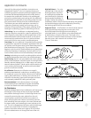
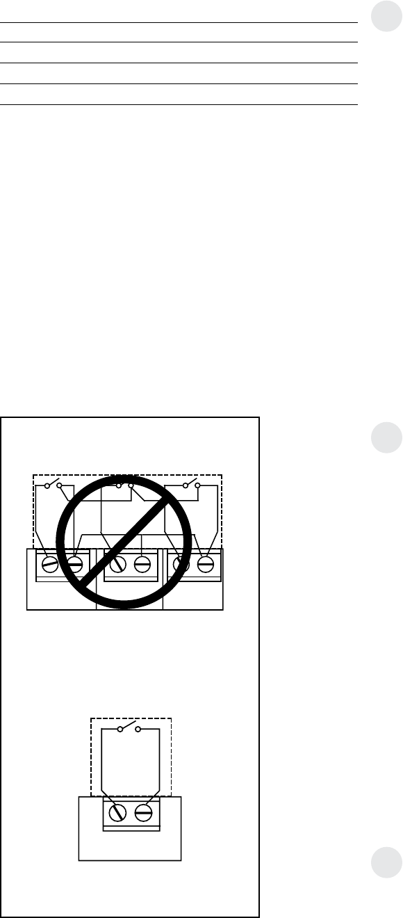
2. Do not use a common bus (at the unit or at the switch
panel) in the wiring. Both wires comprising the circuit
must connect to the unit connectors and to the controlling
switch. Running one wire from one unit to another unit is
common busing and may damage internal components
or cause erratic operation of the system.
3. A 24-volt transformer is contained within the Zoneline unit.
No external voltage may be applied to the unit through
the CDC terminals. (Voltage on the CDC conductors is
24 volts AC.)
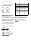
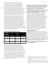
4. Recommended wire size must be followed as a minimum
requirement.
Wire Size #AWG Maximum Allowable Length
#22 600 Ft.
#20 900 Ft.
#18 1500 Ft.
#16 2000 Ft.
Freeze Sentinel
™
and Heat Sentinel remains operational when
the unit is connected to a CDC system. Even if the unit is
turned “OFF” at the central location, if the sensor at the unit
detects the low or high limit temperature, the unit will
automatically turn on until it reaches the preset shutdown
temperature (46°F heating, 80°F cooling).
Connecting the Zoneline unit to a CDC system does not
eliminate the ability to connect the unit to a remote thermostat.
Once the circuit is “opened,” and control of the unit removed
from the CDC system, the selected controls—either the unit—
mounted control or the remote thermostat—govern the
operation of the unit.
Please see page 55 for installation recommendations
for the Central Desk Control wiring.
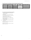
CDC Terminal Location and Typical Wiring
See page 15 for location of CDC terminals on unit.
Unit #2
Unit #1
Unit #3
Example of Common Busing
NOT PERMITTED
CDC Terminals
on Zoneline unit
INCORRECT Common Busing
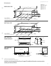
Normally Open
Switch -
Unit Operational
Typical Wiring
(All Wiring Shown Is Field Supplied)