EQUIPMENT APPROVAL INFORMATION
Your telephone equipment is approved for connection to the Public Switched
Telephone Network and is in compliance with parts 15 and 68, FCC Rules and
Regulations and the Technical Requirements for Telephone Terminal Equipment
published by ACTA.
1 Notification to the Local Telephone Company
On the bottom of this equipment is a label indicating, among other
information, the US number and Ringer Equivalence Number (REN) for
the equipment. You must, upon request, provide this information to your
telephone company.
The REN is useful in determining the number of devices you may connect to
your telephone line and still have all of these devices ring when your
telephone number is called. In most (but not all) areas, the sum of the RENs
of all devices connected to one line should not exceed 5. To be certain of the
number of devices you may connect to your line as determined by the REN,
you should contact your local telephone company.
A plug and jack used to connect this equipment to the premises wiring and
telephone network must comply with the applicable FCC Part 68 rules and
requirements adopted by the ACTA. A compliant telephone cord and
modular plug is provided with this product. It is designed to be connected to
a compatible modular jack that is also compliant. See installation instructions
for details.
Notes
• This equipment may not be used on coin service provided by the
telephone company.
• Party lines are subject to state tariffs, and therefore, you may not be
able to use your own telephone equipment if you are on a party line.
Check with your local telephone company.
• Notice must be given to the telephone company upon permanent
disconnection of your telephone from your line.
• If your home has specially wired alarm equipment connected to the
telephone line, ensure the installation of this product does not disable your
alarm equipment. If you have questions about what will disable alarm
equipment, consult your telephone company or a qualified installer.
2 Rights of the Telephone Company
Should your equipment cause trouble on your line which may harm the
telephone network, the telephone company shall, where practicable,
notify you that temporary discontinuance of service may be required.
Where prior notice is not practicable and the circumstances warrant such
action, the telephone company may temporarily discontinue service
immediately. In case of such temporary discontinuance, the telephone
company must: (1) promptly notify you of such temporary discontinuance;
(2) afford you the opportunity to correct the situation; and (3) inform you of
your right to bring a complaint to the Commission pursuant to procedures
set forth in Subpart E of Part 68, FCC Rules and Regulations.
The telephone company may make changes in its communications
facilities, equipment, operations or procedures where such action is
required in the operation of its business and not inconsistent with FCC
Rules and Regulations. If these changes are expected to affect the use or
performance of your telephone equipment, the telephone company must
give you adequate notice, in writing, to allow you to maintain
uninterrupted service.
SEE MARKING ON BOTTOM / BACK OF PRODUCT
RISK OF ELECTRIC SHOCK
DO NOT OPEN
WARNING: TO PREVENT FIRE OR
ELECTRICAL SHOCK HAZARD, DO
NOT EXPOSE THIS PRODUCT TO
RAIN OR MOISTURE.
THE LIGHTNING FLASH
AND ARROW HEAD
WITHIN THE TRIANGLE
IS A WARNING SIGN
ALERTING YOU OF
“DANGEROUS
VOLTAGE” INSIDE THE
PRODUCT.
CAUTION: TO REDUCE THE RISK OF
ELECTRIC SHOCK, DO NOT REMOVE
COVER (OR BACK). NO USER
SERVICEABLE PARTS INSIDE. REFER
SERVICING TO QUALIFIED SERVICE
PERSONNEL.
THE EXCLAMATION
POINT WITHIN THE
TRIANGLE IS A
WARNING SIGN
ALERTING YOU OF
IMPORTANT
INSTRUCTIONS
ACCOMPANYING THE
PRODUCT.
CAUTION:
US Number is located on the cabinet bottom
REN number is located on the cabinet bottom
INTERFERENCE INFORMATION
This device complies with Part 15 of the FCC Rules. Operation is subject to
the following two conditions: (1) This device may not cause harmful
interference; and (2) This device must accept any interference received,
including interference that may cause undesired operation.
This equipment has been tested and found to comply with the limits for a
Class B digital device, pursuant to Part 15 of the FCC Rules. These limits are
designed to provide reasonable protection against harmful interference in a
residential installation.
This equipment generates, uses, and can radiate radio frequency energy
and, if not installed and used in accordance with the instructions, may cause
harmful interference to radio communications. However, there is no
guarantee that interference will not occur in a particular installation.
If this equipment does cause harmful interference to radio or television
reception, which can be determined by turning the equipment off and on, the
user is encouraged to try to correct the interference by one or more of the
following measures:
• Reorient or relocate the receiving antenna (that is, the antenna for radio or
television that is “receiving” the interference).
• Reorient or relocate and increase the separation between the
telecommunications equipment and receiving antenna.
• Connect the telecommunications equipment into an outlet on a circuit
different from that to which the receiving antenna is connected.
If these measures do not eliminate the interference, please consult your
dealer or an experienced radio/television technician for additional
suggestions. Also, the Federal Communications Commission has prepared a
helpful booklet, “How To Identify and Resolve Radio/TV Interference
Problems.” This booklet is available from the U.S. Government Printing
Office, Washington, D.C. 20402. Please specify stock number 004-000-00345-
4 when ordering copies.
FEATURES
• Displays caller’s name and number as well as time and date of
the call.*
• Displays caller’s name and number of the call waiting.
• Three line display.
• Two language display - English and Spanish.
• 15 dot matrix characters used for caller Name and Number service.
• Displays total calls received in standby mode. Stores the CID
information for up to 70 name and number CID records.
• Dials displayed telephone number with area code arrangement.
• Dual review buttons allow forward or backward review of call records.
• Electronic contrast control.
• Delete button allows individual or collective deletion of call records.
• Programmable area code.
• New call indicator.
• Unknown Call, Private Call, Error, and No Data Sent indication.
• Real time clock.
* Requires telephone company provided Caller ID Name and
Number service.
BEFORE YOU BEGIN
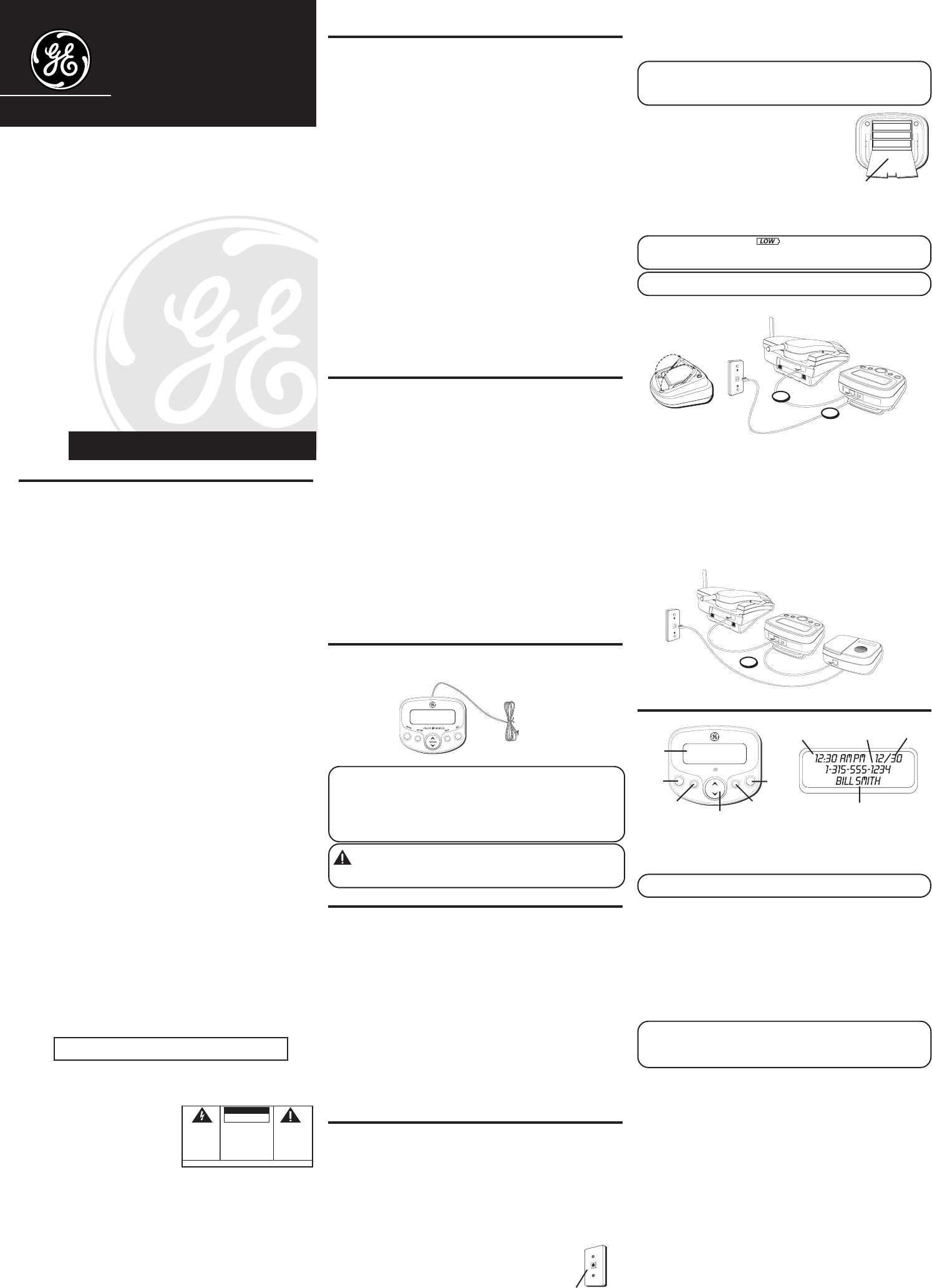
PARTS CHECKLIST
Make sure your package includes the following items:
VERY IMPORTANT: You must call your local phone company and tell the
representative that you have a Caller ID/Call Waiting device that integrates
the two services (called Type II Caller ID). Some phone companies aren't
equipped to integrate the two services, which means only the Caller ID part of
your unit will work. The phone companies that do have the ability to integrate
Call Waiting and Caller ID must program your telephone line so the two
services work together. You need to call and ask them to do this.
CAUTION: When using telephone equipment, there are basic safety
instructions that should always be followed. Refer to the IMPORTANT
SAFETY INSTRUCTIONS provided with this product and save them for
future reference.
INTRODUCTION TO CID SERVICE
Congratulations on purchasing this Caller ID unit. This system
has been designed to be simple to use, however, you can reach
its full potential more quickly by taking a few minutes to read
this User’s Guide.
This Caller ID system is a multifunction product for use with the
Call Waiting and Caller ID services available from your local
telephone company.
YOUR CALLER ID CALL WAITING UNIT ALLOWS
YOU TO:
• View the telephone number and name of a waiting caller (Call
Waiting Caller ID).
• Review all calls to your phone; the unit stores up to 70 call records.
• Screen unwanted calls, eliminate harassment from annoying
calls, or to get prepared before answering a call.
INSTALLATION
IMPORTANT INSTALLATION INFORMATION
• Never install telephone wiring during a lightning storm.
• Never touch uninsulated telephone wires or terminals, unless
the telephone line has been disconnected at the network
interface.
• Use caution when installing or modifying telephone lines.
MODULAR JACK REQUIREMENTS
You need an RJ11C type modular jack, which is the
most common type of phone jack and might look
like the one pictured here. If you don’t have a
modular jack, call your local phone company to find
out how to get one installed.
INSTALLING THE BATTERIES
Your Caller ID uses 3 AA-size alkaline batteries (not included) for receiving
and storing Caller ID records.
IMPORTANT: You have approximately 60 seconds to replace the batteries
before the call records are lost. Please read the instructions before replacing
the batteries and have them ready to be inserted beforehand. You may want to
write down any stored information you do not want erased.
1. Disconnect the telephone line cord from the
modular wall jack. If a phone is connected to the
unit, disconnect it from the unit.
2. Use a screwdriver or other flat tool to open the
battery compartment door.
3. Insert 3 AA-size alkaline batteries (not included)
as shown on the diagram in the battery
compartment.
4. Replace the battery compartment door securely.
5. If the line cord was previously connected, reattach it to the unit.
NOTE: If the low battery icon appears in the display, you need to
replace the batteries. It is important that you replace the batteries as soon as
possible in order to maintain Caller ID operation.
IMPORTANT: If you’re not going to use the unit for more than 30 days,
remove the batteries because they can leak and damage the unit.
CONNECTING A TELEPHONE
1. To install this unit, disconnect your telephone by removing the
plug at the end of its line cord from the telephone wall jack.
2. Plug the line cord from your telephone into the jack marked
PHONE on this unit.
3. Plug the remaining end of the line cord connected to this unit’s
LINE jack into the telephone wall jack.
4. If this unit is connected with an answering machine, please refer
to the following drawing and set your answering machine to
answer the phone for at least 2 rings. This will assure that this
unit will receive the CID information correctly.
OPTIONS MENU
If there is a transparent overlay label covering the display, remove
it prior to use.
When applying power for the first time, the summary screen appears.
NOTE:
Proceed immediately to change any of the following factory preset
settings as required.
1. To enter the options menu, press the options button.
SET
^
or
v
appears.
2.
At this point you can press either arrow button to scroll
through 5 menu screens:
LCD CONTRAST
(default 3)
CID LANGUAGE
(default English)
LOCAL AREA CODE
(default ---)
10 DIGIT AC
’S (default --- --- ---)
EXIT SETUP
NOTE: You have 10 seconds following any key press before the unit
automatically returns to the summary screen.
NOTE: You can save a change by pressing the options button and then exit
the menu by pressing the flash button.
SETTING THE LCD CONTRAST
This adjustment allows you to adjust the contrast and viewing
angle of the display.
1. To enter the options menu, press the options button.
SET
^ or v
appears.
2. Press the up or down arrow button until
LCD CONTRAST
appears.
3. Press the options button to show the current contrast setting.
There are 5 levels of contrast, with the default set to 3.
4. To decrease the contrast, press the down arrow button. To
increase, press the up arrow button.
5. Press options again to store the contrast setting and return to the
LCD CONTRAST
display.
SETTING THE CID LANGUAGE
This adjustment let's you view the Caller ID messages in English or
Spanish.
1. To enter the options menu, press the options button.
SET
^
or
v
appears.
2. Press the up or down arrow button until
CID LANGUAGE
appears.
3. Press the options button to show the current language setting.
The default is English.
We bring good things to life.
29096
Caller ID with Call Waiting
User's Guide
Caller ID unit
Telephone line cord
Model 29096B
00000551 (Rev. 1 E)
04-30
Printed in China
ATLINKS USA, Inc.
101 West 103rd Street
Indianapolis, IN 46290
© 2004 ATLINKS USA, Inc.
Trademark(s) ® Registered
Marca(s) Registrada(s)
Battery door
2
3
Telephone
line jack
Wall plate
u
p
review
CALLERIDMODULE
e
d
el
e
t
po
tios
n
al
fhs
i
d
la
dial
button
flash
button
review button
options
button
delete
button
display
Caller ID name
Caller ID numberTime Date
4


