


1 2
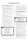
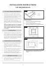
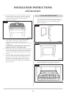
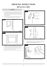
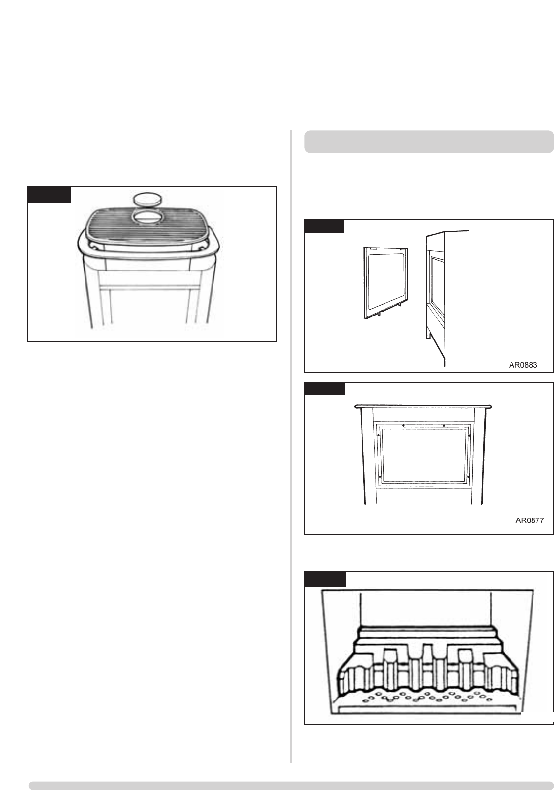
3.10 Place the steel top onto the casing so that the 2 lugs on the
underside locate the top centrally within the casing. Place
the cast iron grille into the recess in the centre of the top
panel and locate the blanking plate into the grill (if
required). See diagram 7.
3.11 Check the pull of the flue system by applying a lighted
smoke pellet to the flue system opening. If there is a
definite flow into the chimney, proceed with the
installation, if not; warm the chimney for a few minutes and
repeat the test.
IF THERE IS STILL NO DEFINITE FLOW, THE FLUE MAY
REQUIRE ATTENTION - SEEK EXPERT ADVICE.
3.12 The flue system may now be connected to the stove, ensure
that all joints are sealed with suitable fire resistant sealant. It
is also recommended that a physical retention method may
be used at the flue spigot joint, self-tapping screws being
favoured.
3.13 Connect a suitable pressure gauge to the test point located
on the inlet fitting, and turn the gas supply on. Light the
appliance and check all gas joints for possible leaks. Turn
the appliance to maximum and check that the supply
pressure is stated on the databadge. Turn the gas off and
replace the test point screw, turn the gas on and check the
test point for leaks.
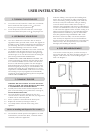
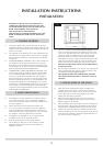
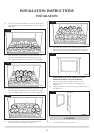
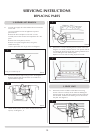
To access the ceramic fuel pieces, it will be necessary to
remove the glass door. Lift off the decorative steel trim, see
Diagram 8 and remove the 6 screws holding the glass
frame. See Diagram 9.
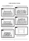
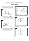
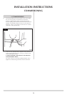
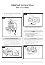
4.1 Place the flame baffle onto the shelf at the rear of the tray
and push up against the rear ledge, see diagram 10.
INSTALLATION INSTRUCTIONS
INSTALLATION
7
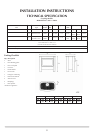
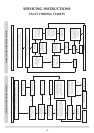
AR0882
4. FUEL BED ARRANGEMENT
8
9
10
AR0365