


Model SC7010B
INTRODUCTION
T
hank you for choosing First Alert
®
f
or your Smoke and Carbon
M
onoxide Alarm needs. You have purchased a state-of-the-art Smoke &
Carbon Monoxide Alarm designed to provide you with early warning of a
f
ire or Carbon Monoxide.
K
ey features include:
Smoke & Carbon Monoxide Combination Alarm.
One alarm protects
a
gainst two deadly household threats.
S
pread Spectrum Horn Tone.
L
ower and varying horn frequency
m
akes it easier for elderly with normal age related hearing loss to hear
h
orn. Sweeps through the 2200 – 3400 Hz range.
S
mart Interconnect
c
an be interconnected to BRK Smoke, CO, and
Heat Alarms. One interconnect wire carries both smoke and CO alarm
s
ignals.
Optipath 360 Technology
T
M
provides 360 degrees of direct access to
t
he smoke sensor.
Single Button Test/Silence eliminates confusion. Depending on what
m
ode the alarm is in, pushing the button provides different functions
s
uch as testing the alarm, silencing the alarm, re-testing the alarm when
in silence and clearing the Latching features.
T
wo Silence Features.
T
emporarily silence low battery chirp for up to
eight hours before replacing low battery or silence an unwanted alarm
f
or several minutes.
T
wo Latching Features.
A
larm Latch: Easily identifies initiating alarm
e
ven after alarm condition has subsided. Low Battery Latch: Identifies
which unit is in low battery condition.
P
erf
ect Mount System
i
ncludes a gasketless base for easy installation
and a mounting bracket that keeps the alarm secur
e
over a wide
r
otation range to allow for perfect alignment.
Dust Cover is included to keep the alarm clean during construction.
E
asy Installation/Maintenance
f
eatures include a large opening in
the mounting bracket for easy access to wiring. A battery pull tab that
k
eeps the battery fre
sh until the home is occupied. A Side Load Battery
D
rawer allows for easy battery replacement without removing the alarm
from the ceiling or wall.
E
nd of Life Signal.
P
ro
vides audible confirmation alarm needs to be
replaced.
Improved UV Resistance keeps the alarm from discoloring over time.
©
2010 BRK Brands, Inc. All rights reserved.
D
istributed by BRK Brands, Inc.
3901 Liberty Str
eet Road, Aur
o
ra, IL 60504-8122
C
onsumer Affairs: (800) 323-9005 • www.firstalert.com
1
SMOKE & CARBON
MONOXIDE ALARM
A
ll First Alert
®
S
moke Alarms conform to regulatory requirements,
i
ncluding UL217 and are designed to detect particles of combustion.
Smoke particles of varying number and size are produced in all
f
ire
s.
I
onization technology is generally more
sensitive than photoelectric
technology at detecting small particles, which tend to be produced
in greater amounts by flaming fires, which consume combustible
m
aterials rapidly and spread quickly. Sources of these fires may include
paper bur
n
ing in a wastebasket, or a gre
ase fire
in the kitchen.
Photoelectric technology is generally mor
e
sensitive than ionization
technology at detecting large particles, which tend to be produced
i
n gre
ater amounts by smoldering fires, which may smolder for
hours before bursting into flame. Sources of these fires may include
cigarettes burning in couches or bedding.
For maximum pr
otection, use both types of Smoke Alar
ms on each
l
evel and in every bedroom of your home.
USER’S MANUAL
AC Powered Smoke & Carbon Monoxide Alarm
F
eatures:
Two Latching Features
S
mart Interconnect
Optipath 360 Technology
T
M
T
wo Silence Features
A
lkaline Battery Backup
IMPORTANT! PLEASE READ CAREFULLY AND SAVE.
T
his user’s manual contains important information about your Alarm’s
operation. If you ar
e
installing the Alarm for use by others, you must
leave this manual—or a copy of it—with the end user.
ELECTRICAL SHOCK HAZARD. Turn off the power to the area
where the Smoke Alarm is installed before removing it from the
mounting bracket. Failure to turn off the power first may result in
serious electrical shock, injury or death.
• This unit will not alert hearing impaired residents.
It is recommended that you install special units which use
devices like flashing strobe lights to alert hearing impaired
residents.
•
Installation of this unit must confor
m to the electrical codes
in your ar
ea; Ar
ticles 210 and 300.3 (B) of NFPA 70 (NEC),
NFPA 72, NFPA 101; SBC (SBCCI); UBC (ICBO); NBC
(BOCA); OTFDC (CABO), and any other local or building
codes that may apply. Wiring and installation must be
per
formed by a licensed electrician. Failure to follow these
guidelines may result in injur
y or pr
oper
ty damage.
•
This unit must be powered by a 24-hour, 120V
AC
pure sine
wave 60Hz circuit. Be sure the circuit cannot be turned
off by a switch, dimmer, or ground fault circuit interrupter.
Failur
e to connect this unit to a 24-hour circuit may pre-
vent it from providing constant protection.
•
This Alarm must have AC or battery power to operate.
If the AC power fails, battery back-up will allow the alarm
to sound for at least 4 minutes. If AC power fails and the
batter
y is weak, protection should last for at least 7 days.
If AC power fails and the battery is dead or missing, the
alarm cannot operate.
• Never disconnect the power from an AC powered unit to
stop an unwanted alar
m. Doing so will disable the unit and
r
emove your protection. In the case of a true unwanted
alarm open a window or fan the smoke away from the unit.
The alar
m will r
eset automatically when it r
eturns to normal
operation. Never remove the batteries from a battery
operated unit to stop an unwanted alarm (caused by cooking
smoke, etc.). Instead open a window or fan the smoke away
from the unit. The alarm will reset automatically.
• Connect this unit ONLY to other compatible units. See
“How To Install This Smoke Alarm” for details. Do not
connect it to any other type of alarm or auxiliary device.
Connecting anything else to this unit may damage it or
pr
event it fr
om operating pr
operly
.
• This Smoke/CO Alarm has a battery drawer which resists
closing unless a battery is installed. This warns you the
unit will not operate under DC power without a batter
y.
• Do not stand too close to the unit when the alarm is
sounding. It is loud to wake you in an emer
gency
. Exposur
e
to the horn at close range may harm your hearing.
• Do not paint over the unit. Paint may clog the openings to
the sensing chambers and prevent the unit from operating
properly.
The Mounting Bracket:
T
o remove the mounting bracket from the Alarm
base, hold the Alarm base firmly and twist the
mounting bracket counterclockwise. The mounting
b
racket installs onto the junction box. It has a
variety of screw slots to fit most boxes.
The Power Connector:
T
he power connector plugs into a power input block
o
n the Alarm. It supplies the unit with AC power.
• The black wire is “hot.”
• The white wire is neutral.
• The orange wire is used for interconnect.
If you need to remove the power connector, turn
POWER OFF first.
Insert a flat screwdriver blade
b
etween the power connector and the security tab
inside the power input block. Gently pry back the tab
and pull the connector free.
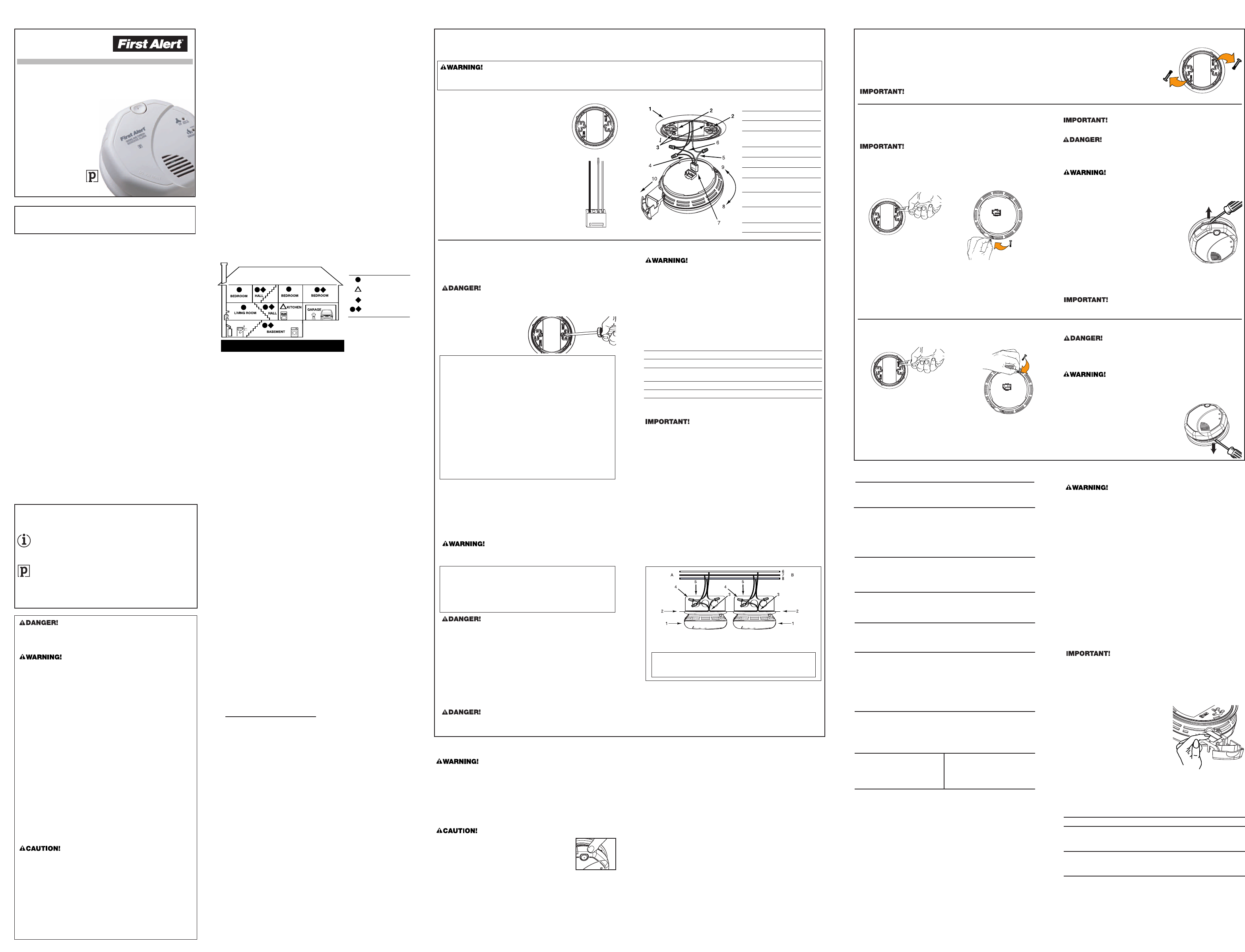
The Parts of This Unit
1
Mounting Bracket
2
Mounting Slots
3 Locking Pins (break out of
b
racket)
4 Hot (Black) AC Wire
5
Neutral (White) AC Wire
6 Interconnect (Orange) Wire
7 Quick-Connect Power
Connector
8
Turn this way to remove
f
rom bracket
9
Turn this way to attach to
bracket
10 Slide-Out Battery Drawer
HOW TO INSTALL THIS SMOKE/CO ALARM
THE PARTS OF THIS ALARM
This Smoke/CO Alarm is designed to be mounted on any standard wiring junction box up to a 4-inch (10 cm) size, on either the ceiling or wall (if allowed
b
y local codes). Read “Where to Install This Alarm” and “Where This Alarm Should Not Be Installed” before you begin installation.
Tools you will need: • Needle-nose pliers or utility knife • Standard flathead screwdriver • Wire strippers.
M
ake sure the Alarm is not receiving excessively noisy power. Examples of noisy power could be major appliances on the same circuit, power
f
rom a generator or solar power, light dimmer on the same circuit or mounted near fluorescent lighting. Excessively noisy power may cause
damage to your Alarm.
The basic installation of this Alarm is similar whether you want to
i
nstall one Alarm, or interconnect more than one Alarm. If you are
i
nterconnecting more than one Alarm, you MUST read “Special
Requirements For Interconnected Alarms” below before you begin
i
nstallation.
E
LECTRICAL SHOCK HAZARD. Tu
rn off power to the area where
you will install this unit at the circuit breaker or fuse box before
b
eginning installation. Failure to turn off the power before installa-
t
ion may result in serious electrical shock, injury or death.
1. Remove the mounting bracket
f
rom the base, and attach it to
t
he junction box.
2.
Using wire nuts, connect the
p
ower connector to the
h
ousehold wiring.
3
. Plug the power connector into the back of the Alarm.
4. Activate the battery back-up by removing the “Pull to Activate
Battery Back-Up” tab. Or
, install battery back-up. Battery back-up
c
annot work until you install the battery in the correct position
(Match “+” to “+” and “-” to “-”).
5.
Position the base of the Alarm over the mounting bracket, and turn
t
he Alarm clockwise (right) until the unit is in place. If wall mounted,
a
djust unit so words are level.
6. Check all connections.
Impr
oper wiring of the power connector or the wiring leading to
t
he power connector will cause damage to the Alarm and may
lead to a non-functioning Alar
m
.
ELECTRICAL SHOCK HAZARD. Do not r
estore power until all
Alarms are completely installed. Restoring power before installation
is complete may result in serious electrical shock, injury or death.
7. Make sure the Alarm is receiving AC power. Under normal
operation, the Green power indicator light will shine continuously.
8. If the Green power indicator light does not light,
TURN OFF
POWER TO THE JUNCTION BOX
and recheck all connections.
If all connections are correct and the Green power indicator still
does not light when you restore the power, the unit should be
replaced immediately.
9. Test each Smoke Alarm. Press and hold the Test/Silence button
until the unit alarms.
When testing a series of interconnected
units you must test each unit individually
. Make sure all units
alarm when each one is tested.
If any unit in the series does not alar
m, TURN OFF POWER and
recheck connections. If it does not alarm when you restore power,
r
eplace it immediately
.
FOLLOW THESE INSTALLATION STEPS
S
TA
ND-ALONE ALARM ONLY:
•
C
onnect the white wire on the power connector to the neutral
wire in the junction box.
• Connect the black wire on the power connector to the hot wire
i
n the junction box.
•
Tuck the orange wire inside the junction box. It is used for
interconnect only.
I
NTERCONNECTED UNITS ONLY
:
S
trip off
about 1/2” (12 mm) of the plastic coating on the orange
wire on the power connector.
• Connect the white wire on the power connector to the neutral
w
ire in the junction box.
•
Connect the black wire on the power connector to the hot wire
in the junction box.
•
Connect the orange wire on the power connector to the
i
nterconnect wire in the junction box. Repeat for each unit you
a
re
interc
onnecting. Never connect the hot or neutral wire
s in the
junction box to the orange interconnect wire. Never cross hot and
n
eutral wires between Alarms.
STAND-ALONE ALARM ONLY:
•
I
f you are only installing one Alarm, restore power to the junction
box.
I
NTERCONNECTED UNITS ONLY:
• If you are interconnecting multiple Alarms, repeat steps
1-5 for each Alar
m in the series. When you ar
e finished,
r
estore power to the junction box.
Special Requirements For Interconnected Alarms
•
Failure to meet any of the above requirements could damage
t
he units and cause them to malfunction, removing your
p
rotection.
•
AC and AC/DC Alarms can be interconnected. Under AC
power, all units will alarm when one senses smoke or CO.
W
hen power is interrupted, only the AC/DC units in the
s
eries will continue to send and receive signals. AC powered
Alarms will not operate.
Interconnected units can provide earlier warning of fire than stand-alone
u
nits, especially if a fire starts in a remote area of the dwelling. If any unit
i
n the series senses smoke, all units will alarm. To determine which Alarm
initiated an alarm, see table:
D
uring an Alarm
:
On Initiating Alarm(s) Red LED(s) flashes (flash) rapidly
On All Other Alarms Red LED is Off
A
fter an Alarm (Latching):
O
n Initiating Alarm(s) Red LED(s) On for 2 seconds/Off for 2 seconds
O
n All Other Alarms Green LED(s) On, Red LED(s) Off
C
ompatible Interc
onnected Units
I
nterc
onnect units within a single family re
sidence only. Otherwise all
households will experience unwanted alarms when you test any unit
i
n the series. Interconnected units will only work if they are wired to
c
ompatible units and all re
quire
ments are
met. This unit is designed to
be compatible with:
BRK Electronics
®
Smoke Alarm Models 9120,
9
120B, SC9120B, 7010, 7010B, 4120, 4120B, 4120SB, 4919, 2002RAC,
1
00S, 5919, 5919TH;
B
RK Electronics
®
H
eat Alarm Models HD6135F,
HD6135FB; BRK Electronics
®
CO Alarm Models CO5120BN,
C
O5120PDBN; Smoke/CO Alarm Model SC6120B, SC7010BV, SC7010B;
a
nd
F
irst Alert
®
S
moke Alarm Models SA4120, SA4120B, SA4121B,
SA4919B, SA100B.
Interconnected units must meet ALL of the following requirements:
•
A
maximum of 18 compatible units may be interc
onnected
(Maximum of 12 Smoke Alarms).
• The same fuse or circuit breaker must power all interconnected
u
nits.
•
T
he total length of wire
interconnecting the units should be
less than 1000 feet (300 meters). This type of wire is commonly
a
vailable at Hardware and Electrical Supply stores.
•
All wiring must conform to all local electrical codes and NFPA 70
(NEC). Refer to NFPA 72, NFPA 101, and/or your local building
c
ode for further connection requirements.
}
}
A. Unswitched 120VAC
60 Hz sour
ce
B
.
T
o additional units; Maximum = 18 total
(Maximum 12 Smoke Alarms)
1. Alarm
2. Ceiling or W
all
3.
Power Connector
4. Wir
e Nut
5. Junction Box
6.
Neutral Wir
e (Wht)
7.
Inter
connect Wir
e
(Orange)
8. Hot Wire (Blk)
2 3 4 5
I
NSTALLATION
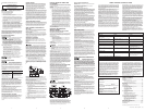
WHERE TO INSTALL THIS ALARM
Minimum coverage for Smoke Alarms, as recommended by the
N
ational Fire Protection Association (NFPA), is one Smoke Alarm on
e
very floor, in every sleeping area, and in every bedroom (See
“Regulatory Information For Smoke Alarms” for details on the NFPA
r
ecommendations).
F
or CO Alarms,
t
he National Fire Protection Association (NFPA)
r
ecommends that a CO Alarm should be centrally located outside of
each separate sleeping area in the immediate vicinity of the bedrooms.
F
or added protection, install additional CO Alarms in each separate
b
edroom, and on every level of your home.
N
OTE:
F
or added protection, install an additional Smoke/CO Alarm at
least 15 feet (4.6 meters) away from the furnace or fuel burning heat
source where possible. In smaller homes or in manufactured homes
w
here this distance cannot be maintained, install the Alarm as far away as
possible from the furnace or other fuel burning source. Installing the Alarm
closer than 15 feet (4.6 meters) will not harm the Alarm, but may increase
t
he frequency of unwanted alarms.
I
n general, install combination Smoke and Carbon Monoxide Alarms:
•
On every level of your home, including finished attics and basements.
• Inside every bedroom, especially if people sleep with the door partly
o
r completely closed.
• In the hall near every sleeping area. If your home has multiple
sleeping areas, install a unit in each. If a hall is more than 40 feet
(
12 meters) long, install a unit at each end.
• At the top of first-to-second floor stairs.
• At the bottom of the basement stairs.
•
For additional coverage, install Alarms in all rooms, halls, and storage
areas, where temperatures normally remain between 40˚ F and 100˚ F
(4˚ C and 38˚ C).
RECOMMENDED PLACEMENT
• When installing on the wall, the top edge of Smoke Alarms should
b
e placed between 4 inches (102 mm) and 12 inches (305 mm) from
t
he wall/ceiling line.
•
When installing on the ceiling, place the alarm as close to the center
as possible.
• In either case, install at least 4 inches (102 mm) from where the
w
all and ceiling meet. See “Avoiding Dead Air Spaces” for more
i
nformation.
N
OTE:
F
or any location, make sure
no door or other obstruction could
keep carbon monoxide or smoke from reaching the Alarm.
I
nstalling Smoke/CO Alarms in Mobile Homes
For minimum security install one Smoke/CO Alarm as close to each
s
leeping area as possible. For more security, put one unit in each room.
Many older mobile homes (especially those built before 1978) have little
or no insulation. If your mobile home is not well insulated, or if you ar
e
u
nsure of the amount of insulation, it is important to install units on
inside walls only.
WHERE THIS ALARM SHOULD NOT BE INSTALLED
Do NOT locate this Smoke/CO Alar
m:
• In garages, furnace rooms, crawl spaces and unfinished attics.
A
void extremely dusty, dirty or greasy areas.
• Where combustion particles are produced. Combustion particles
f
orm when something burn
s. Areas to avoid include poorly ventilated
kitchens, garages, and furnace rooms. Keep units at least 20 feet
(6 meters) from the sources of combustion particles (stove, furnace,
w
ater heater, space heater) if possible. In areas where a 20-foot
(6 meter) distance is not possible – in modular
,
mobile, or smaller
homes, for example – it is recommended the Smoke Alarm be
p
laced as far from these fuel-burning sources as possible. The
placement recommendations are intended to keep these Alarms at
a reasonable distance from a fuel-burning source, and thus reduce
“
unwanted” alarms. Unwanted alarms can occur if a Smoke Alarm is
placed directly next to a fuel-burning source. Ventilate these areas
as much as possible.
• Within 5 feet (1.5 meters) of any cooking appliance. In air streams
n
ear kitchens. Air currents can draw cooking smoke into the smoke
s
ensor and cause unwanted alarms.
•
In extremely humid areas. This Alarm should be at least 10 feet (3
meters) from a shower, sauna, humidifier, vaporizer, dishwasher,
laundry room, utility room, or other sour
ce of high humidity.
•
In dir
ect sunlight.
•
In turbulent air, like near ceiling fans or open windows. Blowing air
may prevent CO or smoke from r
eaching the sensors.
•
In ar
eas where temperature is colder than 40˚ F (4˚ C) or hotter than
100˚ F (38˚ C). These areas include non-airconditioned crawl spaces,
unfinished attics, uninsulated or poorly insulated ceilings, porches,
and garages.
• In insect infested areas. Insects can clog the openings to the sensing
chamber.
• Less than 12 inches (305 mm) away from fluorescent lights.
Electrical “noise” can interfere with the sensor.
• In “dead air” spaces. See “Avoiding Dead Air Spaces”.
A
VOIDING DEAD AIR SPACES
“Dead air” spaces may prevent smoke from reaching the Smoke/CO
Alarm. To avoid dead air spaces, follow installation recommendations
below
.
On ceilings, install Smoke/CO Alarms as close to the center of the
ceiling as possible. If this is not possible, install the Smoke/CO Alarm
at least 4 inches (102 mm) fr
om the wall or cor
ner.
For wall mounting (if allowed by building codes), the top edge of
Smoke/CO Alarms should be placed between 4 inches (102 mm) and
12 inches (305 mm) fr
om the wall/ceiling line, below typical “dead air”
spaces.
On a peaked, gabled, or cathedral ceiling, install first Smoke/CO
Alarm within 3 feet (0.9 meters) of the peak of the ceiling, measur
ed
horizontally. Additional Smoke/CO Alarms may be required depending
on the length, angle, etc. of the ceiling's slope. Refer to NFP
A 72 for
details on requirements for sloped or peaked ceilings.
SUGGESTED AREAS FOR INSTALLING
SMOKE ALARMS, CO ALARMS, AND COMBO UNITS
SMOKE ALARM WITH
S
ILENCE FEATURE
CO ALARMS
B
OTH, OR COMBINATION
S
MOKE/CO ALARMS
S
MOKE ALARMS
KEY:
S
uggested locations are based on
NFPA recommendations (NFPA 72
for Smoke Alarms and NFPA 720 for
Carbon Monoxide Alarms). Always
refer to national and local codes
b
efore beginning any installation.
In new construction AC and AC/DC smoke alarms MUST
be interconnected to meet NFPA recommendations.
LOCKING FEATURES
T
he locking features are designed to discourage unauthorized removal of the batteries or Alarm. It is not necessary to activate the locks in
single-family households where unauthorized battery or Alarm removal is not a concern.
T
hese Alarms have two separate locking features: one to lock the battery compartment, and the other to lock the Alarm
to the mounting bracket. You can choose to use either feature independently, or use them both.
Tools you will need: • Needle-nose pliers • Standard Flathead screwdriver.
B
oth locking features use locking pins, which are molded into the mounting bracket. Using needle-nose pliers, remove
one or both pins from the mounting bracket, depending on how many locking features you want to use.
To permanently remove either lock, insert a flathead screwdriver between the locking pin and the lock, and pry the pin out of the lock.
TO LOCK THE BATTERY COMPARTMENT
Do not lock the battery compartment until you have installed the
battery and tested the battery back-up.
1
. Push and hold Test/Silence button until the alarm sounds.
If the unit does not alarm during testing, DO NOT lock the battery
compartment! Install a new battery and test again. If the Alarm still
d
oes not alarm, replace it immediately.
2. Using needle-nose pliers, detach one locking pin from the mounting
b
racket.
3
. Push the locking pin through the hole near the battery drawer on
t
he back of the Alarm.
T
O UNLOCK THE BATTERY COMPARTMENT
O
nce the Alarm is installed, you must disconnect it from the AC power
before unlocking the battery compartment.
ELECTRICAL SHOCK HAZARD. Turn off the power to the area where
the Alarm is installed before removing it from the mounting bracket.
F
ailure to turn off the power first may result in serious electrical
shock, injury or death.
A
lways discharge the branch circuit before servicing an AC or AC/DC
Alarm. First, turn off the AC power at the circuit breaker or fuse box.
Next, remove the battery from Alarms with battery back-up. Finally,
p
ress and hold the Test/Silence button for 5-10 seconds to discharge
the branch circuit.
1. Remove the Alarm from the mounting bracket.
I
f the unit is locked to the bracket, see the
section “To Unlock the Mounting Bracket.”
2. Disconnect the power connector by gently
prying it away from the back of the Alarm.
3. Insert a flathead screwdriver under the head
o
f the locking pin, and gently pry it out of the
battery compartment lock. (If you plan to
relock the battery compartment, save the
l
ocking pin.)
4
. To relock the battery compartment, close the battery door and
r
einsert locking pin in lock.
5
. Reconnect the power connector to the back of the Alarm, reattach
t
he Smoke Alarm to the mounting bracket, and restore the power.
W
hen replacing the batteries, always test the Alarm before relocking
t
he battery compartment.
TO UNLOCK THE MOUNTING BRACKET
ELECTRICAL SHOCK HAZARD. Turn off the power to the area where
t
he Alarm is installed before removing it from the mounting bracket.
F
ailure to turn off the power first may result in serious electrical
shock, injury or death.
A
lways discharg
e the branch circuit before servicing an AC or AC/DC
Alarm. First, turn off the AC power at the circuit breaker or fuse box.
N
ext, remove the battery from Alarms with battery back-up. Finally,
p
ress and hold the Test/Silence button for 5-10 seconds to discharge
the branch circuit.
1. Insert a flathead screwdriver between the
m
ounting bracket pin and the mounting
b
racket.
2. Pry the Alarm away from the bracket by
t
ur
n
ing both the screwdriver and the Alarm
c
ounterc
lockwise (left) at the same time.
TO LOCK THE MOUNTING BRACKET
1
. Using needle-nose pliers, detach one locking pin from mounting
bracket.
2
. I
nsert the locking pin into the lock located
o
pposite from the battery drawer as
shown in the diagram.
3
. W
hen you attach the Alarm to the mounting bracket, the locking
p
in’s head will fit into a notch on the bracket.
WHAT YOU WILL SEE AND HEAR WITH THIS ALARM
Under Nor
mal Operations
H
orn
:
S
ilent
P
ower/Smoke LED:
C
onstant Gre
en
C
O LED:
O
ff
W
hen You Test the Alarm
H
orn:
3
beeps, pause, 3 beeps
Power/Smoke LED: Flashes Red in sync with the horn pattern
C
O LED:
O
ff, followed by
Horn: 4 beeps, pause, 4 beeps
P
ower/Smoke LED:
O
ff
CO LED: Flashes Red in sync with the horn pattern
If Battery Becomes Low or is Missing
H
orn:
c
hirps once a minute
Power/
Smoke LED:
Flashes Gr
een On for 2 seconds/Off for
2 seconds. Low Battery Latch is now engaged.
CO LED: Off
I
f Alarm is Not Operating Properly (MALFUNCTION SIGNAL)
H
orn:
3
chirps every minute
P
ower/Smoke LED:
3
Flashes appro
ximately once a minute
CO LED: Off
Alarm has reached its End of Life
Horn: 5 chirps every minute
Power/Smoke LED: 5 Flashes approximately once a minute
CO LED: Off
Alarm Levels of CO ar
e Detected
Horn:
4 beeps, pause, 4 beeps*
Power/Smoke LED: Off
CO LED: During Alarm: Flashes Red in sync with the horn pattern.
After Alarm: Flashes Red On for 2 seconds/Off for 2
seconds. CO Alarm Latch is now engaged.
*NOTE: If unit goes into CO alarm, the regular 4 beeps-brief pause
cycle will repeat for fifteen minutes. After fifteen minutes, the pause
will increase to one minute.
Smoke is Detected
Horn: 3 beeps, pause, 3 beeps
Power/Smoke LED: During Alarm: Flashes Red in sync with the
horn pattern. After Alarm: Flashes Red On for 2 seconds/Off
for 2 seconds. Smoke Alarm Latch is now engaged.
CO LED: Of
f
Smoke Alarm is Silenced
Hor
n:
Of
f
Power/Smoke LED: Flashes
Red
CO LED: Off
CO Alarm is Silenced
Hor
n:
Of
f
Power/Smoke LED: Of
f
CO LED: Flashes Red
WEEKL
Y TESTING
•
NEVER use an open flame of any kind to test this unit. You
might accidentally damage or set fir
e to the unit or to your
home. The built-in test switch accurately tests the unit’
s
operation as required by Underwriters Laboratories, Inc. (UL).
NEVER use vehicle exhaust! Exhaust may cause per
manent
damage and voids your warranty.
•
If the Alar
m ever fails to test pr
operly
, r
eplace it immediately.
Pr
oducts under warranty may be returned to the manufacturer
for replacement. See “Limited Warranty” at the end of this
manual.
It is important to test this unit every week to make
sur
e it is working pr
operly. Using the test button is
the recommended way to test this Smoke/CO Alarm.
You can test this Smoke/CO Alarm by pressing and
holding the Test/Silence button on the Alarm cover.
During testing, you will see and hear the following
sequence:
• The Horn will sound 3 beeps, pause, 3 beeps. The Power/Smoke
LED flashes Red and the CO LED will be Of
f.
• Next the
Horn will sound 4 beeps, pause, 4 beeps. The Power/
Smoke LED
will be Off and the CO LED flashes Red.
If the unit does not alarm, make sure the batteries are correctly
installed, and test again. If the unit still does not alarm, replace it
immediately
.
2
1
6
REGULAR MAINTENANCE
Use only the replacement batteries listed below. The unit may not
o
perate properly with other batteries. Never use r
echargeable
b
atteries since they may not provide a constant charge.
This unit has been designed to be as maintenance-free as possible, but
t
here are a few simple things you must do to keep it working properly:
• Test it at least once a week.
•
C
lean the Smoke/CO Alarm at least once a month; gently vacuum
the outside of the Smoke/CO Alarm using your household vacuum’
s
s
oft brush attachment. Test the Smoke/CO Alarm. Never use water,
cleaners or solvents since they may damage the unit.
•
If the Smoke/CO Alarm becomes contaminated by excessive dirt,
dust and/or grime, and cannot be cleaned to avoid unwanted
alarms, r
eplace the unit immediately
.
• Relocate the unit if it sounds frequent unwanted alarms. See “Where
T
his Alarm Should Not Be Installed” for details.
• When the battery back-up becomes weak, the Alarm will “chirp”
a
bout once a minute (the low battery warning). This warning should
last 7 days, but you should r
eplace the battery immediately to
continue your protection. The Low Battery Latch feature will be
e
ngaged. The Gre
en Power/Smoke LED will flash On for 2 seconds/
Off for 2 seconds.
Choosing a replacement battery:
Your Smoke/CO Alarm requires two “AA” Energizer E91 batteries.
These batteries ar
e available at many local retail stores.
Actual battery service life depends on the Alarm and the envir
onment
in which it is installed. All the batteries specified above are acceptable
replacement batteries for this unit. Regardless of the manufacturer’s
suggested battery life,
you MUST replace the battery immediately
once the unit starts “chirping” (the “low battery warning”).
To replace the batteries (without removing Alarm from the ceiling
or wall):
1. Open the battery compartment.
2. Press tabs A and B as shown in the
diagram and remove each battery.
3. Insert the new batteries, making sure
they snap completely into the battery
compartment. Match the terminals on
the ends of the batteries with the
terminals on the unit.
4. Close the battery compartment, and
then test the unit by pressing the
Test/Silence button.
A
B
T
ype of Alar
m
Carbon Monoxide (CO)
What Y
ou See and Hear
Horn:
4 beeps, pause, 4 beeps
Power/Smoke LED: Off
CO LED: Flashes Red
Smoke
Horn: 3 beeps, pause, 3 beeps
Power/Smoke LED: Flashes Red
CO LED: Off
IF YOUR SMOKE/CO ALARM SOUNDS
WHAT TO DO FIRST–
IDENTIFY THE TYPE OF ALARM SIGNAL
Continued...
Printed in Mexico
M08-0182-009
K1
09/10
L
ISTED TO
UL 217 and
U
L 2034
STANDARDS