


8 Installation instructions and Owner’s Manual
70574 REV. C 8/05
WARNING: This appliance requires a 3/8” NPT
(National Pipe Thread) inlet connection to the
pressure regulator. Use of floor mounting feet will
require you to use a 3/8 NPT street elbow to make
gas connection.
CAUTION: Never connect heater to private (non-utility)
gas well. This gas is commonly known as well-head
gas.
IMPORTANT: Check your gas line pressure before
connecting heater to gas line. Gas line pressure must
be no greater than 14 inches of water. If gas line
pressure is higher, heater regulator damage could
occur.
CAUTION: Use only new black iron or steel pipe.
Internally-tinned copper tubing may be used in certain
areas. Check your local codes. Use pipe of larger
enough diameter to allow proper gas volume to heater.
If pipe is too small, undue loss of pressure will occur.
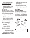
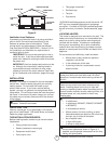
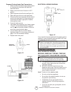
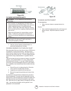
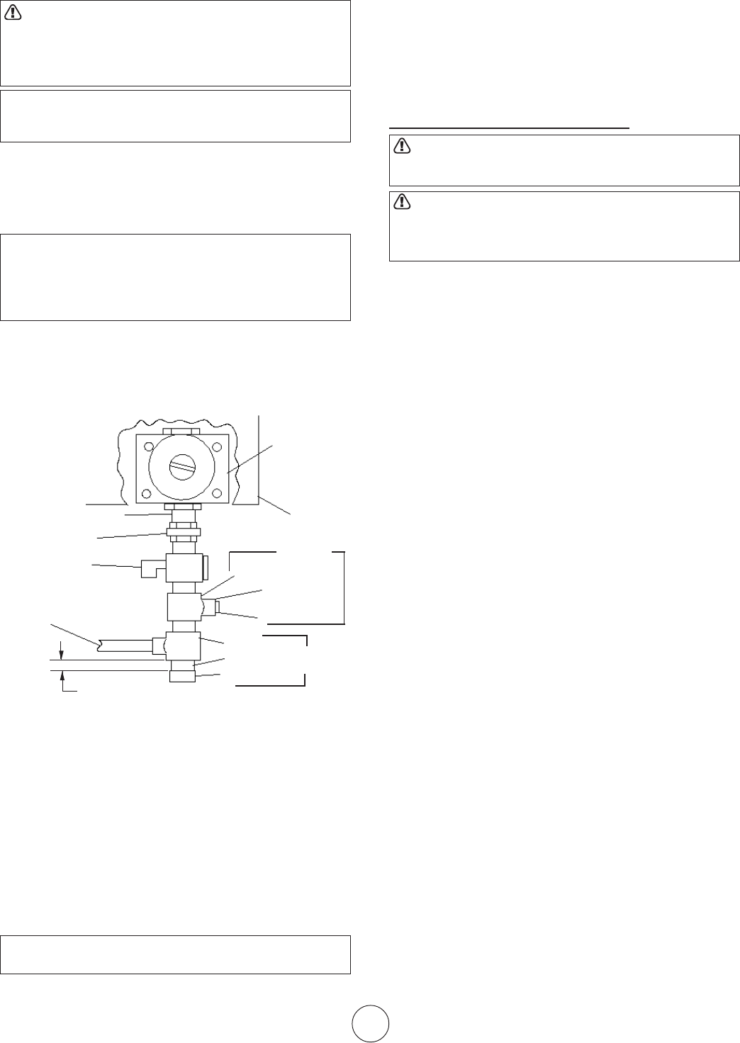
Installation must include an equipment shutoff valve,
union and plugged 1/8” NPT tap. Locate NPT tap within
reach of test gauge hookup. NPT tap must be upstream
from heater (see figure 12).
Figure 12
*A CSA/AGA certified equipment shutoff valve with 1/8”
NPT tap is an acceptable alternative to test gauge
connection. Purchase the CSA/AGA certified equip-
ment shutoff valve from your dealer. See Accessories,
page 17.
IMPORTANT: Install an equipment shutoff valve in an
accessible location. The equipment shutoff valve is for
turning on or shutting off the gas to the appliance.
Apply pipe joint sealant lightly to male threads. This will
prevent excess sealant from going into pipe. Excess
sealant in pipe could result in clogged heater fuel train.
CAUTION: Use pipe joint sealant that is resistant to
natural gas.
Install sediment trap in supply line as shown in figure
12. Locate sediment trap where it is within reach for
cleaning. A sediment trap traps moisture and contami-
nants. This keeps them from going into heater. If
sediment trap is not installed or is installed improperly,
heater may not run correctly.
IMPORTANT: Hold pressure regulator with wrench
when connecting it to gas piping and/or fittings.
CHECKING GAS CONNECTIONS
WARNING: Test all gas piping and connections for
leaks after installing or servicing. Correct all leaks
at once.
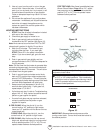
WARNING: Never use an open flame to check for a
gas leak. Apply a mixture of liquid soap and water to
all joints. Bubbles forming show a leak. Correct all
leaks at once.
PRESSURE TESTING GAS SUPPLY PIPING
SYSTEM
Test pressure in Excess of ½ psig (3.5kPa)
1. Disconnect appliance with its appliance main
gas valve (control valve) and equipment shutoff
valve from gas supply piping system. Pres-
sures in excess of ½ psig will damage heater
regulator.
2. Cap off open end of gas pipe where equipment
shutoff valve was connected.
3. Pressurize supply piping system by either using
compressed air or opening main gas valve on
or near gas meter.
4. Check all connections and joints in gas supply
piping system. Apply mixture of liquid soap and
water to gas joints. Bubbles forming show a
leak.
5. Correct all leaks at once.
6. Depressurize and relieve pressure in supply
piping system.
7. Reconnect heater and equipment shutoff valve
to gas supply.
8. Reconnected fittings must be checked for leaks
in next section.
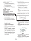
Test Pressure Equal To or Less Than ½ psig (3.5 kPa)
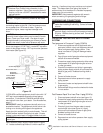
1. Close equipment shutoff valve (see figure 13).
2. Pressurize supply piping system by either using
compressed air or opening main gas valve on
or near gas meter.
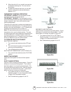
3. Check all joints from the gas meter to equip-
ment shutoff valve (see figure 14). Apply
mixture of liquid soap and water to gas joints.
Bubbles forming show a leak.
4. Correct all leaks at once.
5. Depressurize and relieve pressure from supply
piping system.
Pressure
Regulator
Heater
Cabinet
Ground Joint Union
Equipment
Shutoff Valve
From Gas Meter
(4” W.C. to 10.5”
W.C. Pressure)
Tee Joint
1/8” NPT Plug Tap
Cap
Pipe Nipple
Tee Joint
3/8” NPT Pipe Nipple
Sediment
Trap
Test Gauge
Connection
Reducer Bushing
to 1/8” NPT
3” Minimum