


Page 19
12409-2-0403
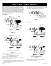
WIRING
Millivolt Control
The valve regulator controls the burner pressure which should be
checked at the pressure test point. Turn captured screw counter
clockwise 2 or 3 turns and then place tubing to pressure gauge
over test point (Use test point “A” closest to control knob). After
taking pressure reading, be sure and turn captured screw clock-
wise firmly to re-seal. Do not over torque. Check for gas leaks.
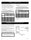
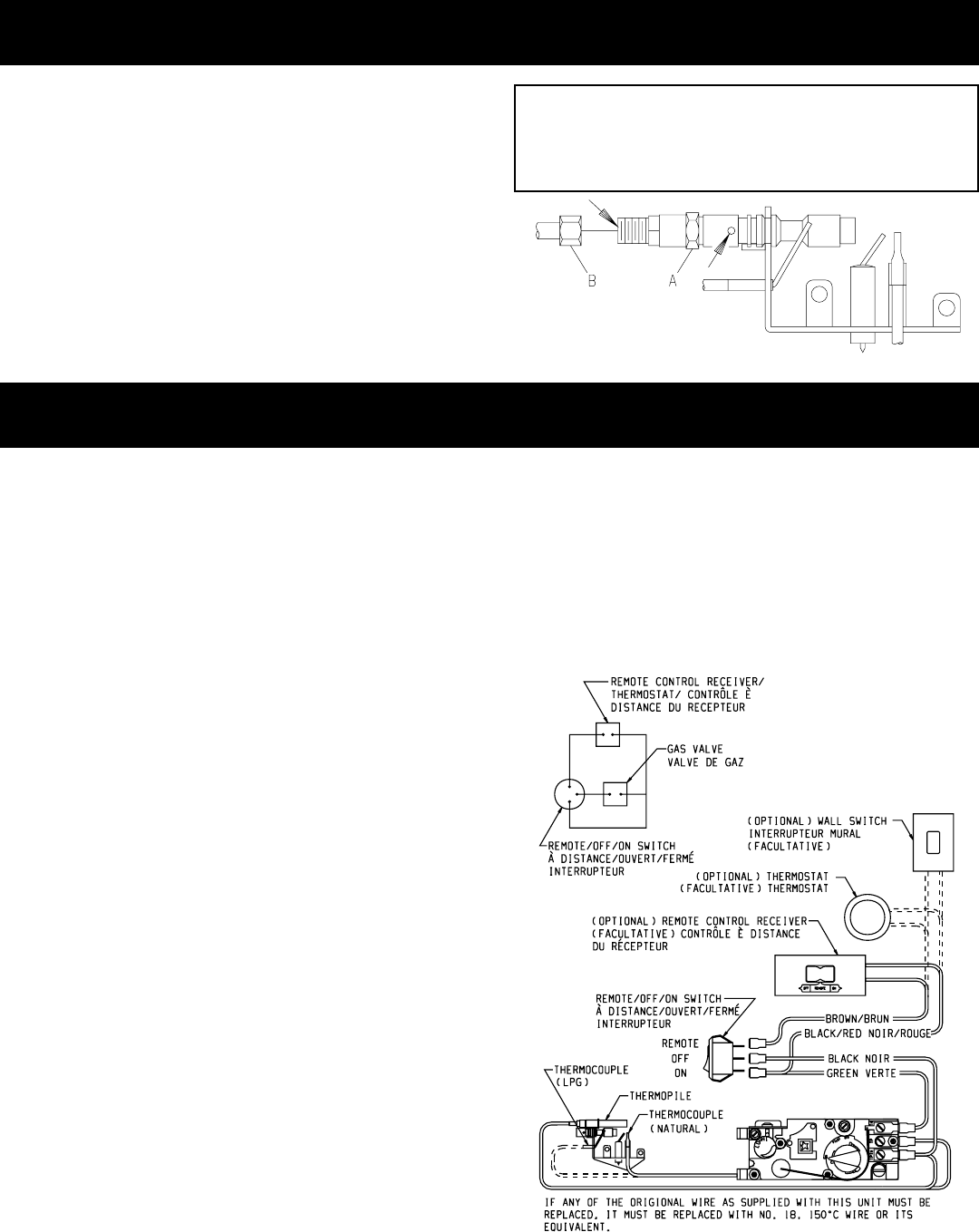
Wiring Diagram (Figure 25)
Label all wires prior to disconnection when servicing controls.
Wiring errors can cause improper and dangerous operation. Verify
proper operation after servicing.
16", 18", 24" and 30" Gas Logs (Millivolt) thermopile is self pow-
ered gas valve and does not require 110 volts. Refer to (Figure
25) to provide optional wall switch, thermostat, or remote con-
trol. Maximum length of 20 feet of 18 AWG to conductor wires is
to be used with all optional switches.
Use the two leads (Red and Green wires) to attach optional com-
ponents.
Check System Operation
Millivolt system and all individual components may be checked
with a millivolt meter 0-1000 MV range.
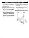
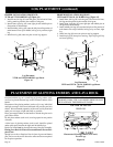
Remote Receiver -VFYR-(16, 18, 24, 30)
Use the following steps to place the remote receiver adjacent to
the gas valve.
Attention:
1. The remote receiver can not be placed behind the gas valve
and burner assembly.
2. When facing the appliance, the remote receiver must be placed
to the right of the gas valve and burner assembly.
Note: Do not let remote control receiver come in contact with
burner assembly.
On circulating vent-free firebox, install remote control receiver
behind bottom louver.
Refer to remote control installation and operating instructions for
more details on remote control.
750 Millivolt System
When you ignite the pilot, the thermocouple produces millivolts
(electrical current) which energizes the magnet in the gas valve.
After 30 seconds to 1 minute time period you can release the gas
control knob and the pilot will stay ON. Allow your pilot flame
to operate an additional one (1) to two (2) minutes before you turn
the gas control knob from the PILOT position to the ON position.
This time period allows the millivolts (electrical current) to build-
up to a sufficient level allowing the gas control to operate
properly.
Figure 25
Cleaning and Maintenance/Pilot
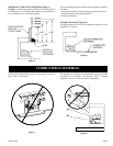
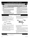
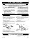
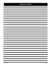
Oxygen Depletion Sensor Pilot (Figure 24)
When the pilot has a large yellow tip flame, clean the Oxygen
Depletion Sensor as follows:
1. Clean the ODS pilot by loosening nut B from the pilot
tubing. When this procedure is required, grasp nut A with
an open end wrench.
2. Blow air pressure through the holes indicated by the arrows.
This will blow out foreign materials such as dust, lint and
spider webs. Tighten nut B also by grasping nut A.
Warning:
Never use needles, wires, or similar cylindrical objects
to clean the pilot to avoid damaging the calibrated ruby
that controls the gas flow.
Figure 24
PILOT FLAME CHARACTERISTICS (continued)