


12426-4-0104 Page 17
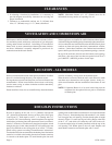
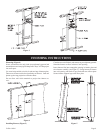
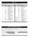
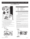
No. Number Description
1 GW- 130 Remote Bulb Control Kit
2 R-1224 Remote Bulb Control
3 R-2499 Wire Assembly
4 R-1162 Control Knob
5 R-1720 Plastic Clip (3 Required)
6 R-1223 Instructions
7 R-1578 No. 6-32 x 1/4" (6mm) Screw (2 Required)
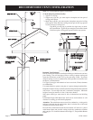
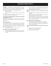
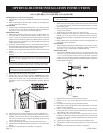
Caution: Remote bulb wire routing is important. Wires should be
in proper location to avoid damage from being overheated.
Incorrect routing of remote bulb control wires may result
in damage to wires and incorrect operation of remote bulb
control. Follow these instructions and refer to the drawing
for proper wire routing.
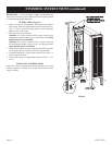
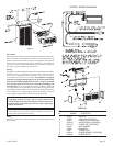
7. If remote bulb control is located on the right side of the outer cas-
ing, carefully bend or loop capillary wire around control. This will
enable the sensing bulb to be positioned at the bottom of the unit.
8. Secure sensing bulb on the inside, at the bottom, of the outer casing
with (2) plastics clips.
9. Feed the wire assembly down along the inside of the outer casing.
10. Use third plastic clip to secure wire assembly and capillary wire to
the casing. (Approximately 24" (610mm) from bottom of unit.)
11. Attach control knob to remote bulb control.
12. Install furnace according to instructions in the Installation Instruc-
tions and Owner's Manual.
Note: If wall furnace is already installed, secure outer casing to
unit.
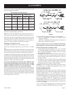
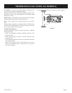
13. Attach wire assembly to gas valve at the "TH" and "TH/TP" terminals
on the Robertshaw valve.
Attach wire assembly to gas valve at the "THERMO" terminals on
the ITT valve. If the wire assembly has two 1/4" (6mm) female
connectors, the connectors should be cut off the wire assembly. Strip
and bare the wires and attach wires to the "THERMO" terminals.
Note: This remote bulb control is connected to the gas valve the
same way as a wall thermostat. Any references made to the ther-
mostat in the lighting instructions would also apply to the remote
bulb control.
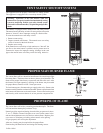
INSTRUCTIONS
Note: At the option of the owner, the remote bulb control may be
located on the left or right side of the outer casing.
1. Remove remote bulb control from the shipping carton.
2. Remove outer casing assembly from shipping carton.
Note: If wall furnace is already installed, remove outer casing from
unit and lay on ß oor with front side down.
3. Attach wire assembly to remote bulb control.
4. Carefully unwind capillary wire on remote bulb control.
5. Remove (3) hole plugs from left or right side of outer casing where
remote bulb control is to be installed.
6. Mount remote bulb control to inside of outer casing with (2) No. 6-32
x 1/4" (6mm)screws.
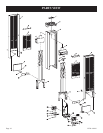
Index Part
TO VENT SAFETY
TO VENT SAFETY
TO REMOTE BULB
TO REMOTE BULB
TO THERMOPILE
TO
THERMOPILE
MODELS
GWT-25 RB, GWT-35 RB, GWT-50 RB
REMOTE BULB CONTROL INSTALLATION INSTRUCTIONS