


Page 1R-3088
SUPERB GAS STOVES
R-3088
Assembly Instructions
Effective Date November, 2003
WARNING
If not assembled, operated and maintained in accordance with
the manufacturers instructions, this product could expose you to
property damage, personal injury or loss of life from fire,
explosion or asphyxiation.
Read all warnings below.
W
ARNING
1. The following model numbers are for indoor or outdoor use in
Canada. The following model numbers are for outdoor use only
in United States.
ES-100, ES-200, ES-300,
MS-100, MS-200, MS-300,
ES-S100, ES-S200, ES-S300.
Attention: Portable (20 lb.) cylinder can not be used indoors.
The following model numbers are for outdoor use only in
Canada and United States.
SE-200 and SE-300.
2. Do not leave appliance unattended while in use or hot. Never
move cooker while in use or hot.
3. A fire can occur from overheated oil or grease.
4. Oil may heat faster than expected.
5. Use a thermometer to monitor oil temperature.
6. Do not use appliance on or near combustible surfaces, wood
decks, storage sheds, garages, shrubbery, trees, houses, etc...
7. Do not cover the pot when heating oil or grease.
8. Should grease fire occur, turn off the gas and cover the pot with
the lid.
9. Check every fitting for gas leaks before each use.
10. Never stand over burner while lighting; this could result in serious
injury. Carefully follow lighting instructions.
11. Keep children and pets at a safe distance.
12. Never place empty containers over an open flame.
13. Do not attempt to change valve depth into burner or reassemble
parts.
14. Never store propane tank in an enclosed area. If cooker is stored in
doors after use, disconnect the propane tank for outdoor storage.
15. The Superb regulator and hose assembly must be used, no
substitutions. Other regulators or no regulator used at all could
result in dangerous gas leakage and improper burner performance.
16. Never install or remove the propane tank while cooker is in use or
too hot to touch.
17. Always inspect hose kit before each use. Protect hose from cuts,
heat or abrasions. Never use a hose that indicates signs of cracking
or damage.
18. Never allow hose to contact any part of the cooker while in use or
still hot. Place propane tank from cooker so that the hose length
will not be in the way. Keep all connections and fittings clean,
replace any damaged parts.
19. Never store the propane tank near high heat, open flames, direct
sunlight or where high temperature exist.
Assembly Instructions
REQUIRED TOOLS: Pliers or adjustable wrench and screwdriver.
1. Bolt legs in place by inserting short bolts through holes in corners
of main top, then through slot at top of leg. Screw nuts onto the
bolts. Attach drip pan using four of the short bolts. Insert bolts
through hole in center of leg and through corner of pan. Apply nuts
and tighten securely. Now tighten leg bolts.
2. Install manifold clamps. Insert two long bolts through manifold
clamp holes in the main top. Attach the two manifold clamps loosely
underneath top, using nuts. Place manifold pipe with valves attached
into the clamps. Align the gas valves with center of large opening in
top. The adjusting hood of the valve should face the rear of the
stove. Now tighten the manifold clamps securely. Place the valve
knobs on valve stem, making sure that the control valve is in the off
position. Knob should be in the vertical position. Manifold Pipe
thread is 3/8 male IPS.
3. To install burners: If stove is to be used with LP or bottled gas, the
air shutter (round metal disc) should be partially opened and then
locked in place by tightening the air shutter screw. The hole in open
end of burner slides over the adjusting hood of the gas valve. The
rear part of the burner is attached to hole underneath main top using
long bolts with nuts. Fasten securely.
4. The grates are installed by inserting the two extended legs on grate
into corresponding holes in main top on each side of burner
opening.
5. Always use teflon tape or thread sealer on pipe threads.
FOR MINI-STOVE MODELS (NUMBER MS-100, MS-200, MS-
300))
6. Remove the main top by pulling upward. Install the two manifold
clamps, using the long bolts with nuts, to the bottom front of frame.
Do not tighten clamps.
7. Insert the manifold pipe with valves attached into the clamps; open
end of manifold should extend through hole in left side of frame.
Tighten the manifold clamps. Burners are fastened to burner hangers
already installed. Then assemble in same manner as above.
CHECK FOR GAS LEAKS
After assembly is complete, connect stove to gas supply and check for
gas leaks before lighting. Make sure
proper fittings are used for connection.
(To operate gas valve, push in before
turning.)
1. Turn brass control valve so knob is
in vertical position until it is tight.
(This shuts off flow of gas from the
regulator to the burner.
2. Open LP cylinder valve or gas
supply by 1/4 turn. This allows gas
into the regulator and stops it at the
brass control valve.
3. Apply gas detector fluid (or soapy
dishwashing solution) on all
connections, especially around the
regulator, valve and POL-cylinder
connection. Any bub-bles that appear indicate a gas leak. If so,
turn off gas and tighten the fitting. If a leak persists, pipe thread
compound may be needed on the threads.
NEVER USE
A FLAME TO CHECK FOR GAS LEAKS.
TO LIGHT
1. When you are sure there are no gas leaks,
turn cylinder valve and brass control valve
to closed position.
(To operate gas valve, push in before
turning.)
2. Re-open LP cylinder valve fully.
3. Re-open brass control valve 1/4 turn.
4. Keeping hands and face away from the top of the burner, light with
a fireplace match or long-nose lighter.
5. Adjust the brass control valve for desired flame height.
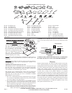
WRENCH TIGHTENED ASSEMBLY
Regulator
POL Connector
Cylinder Service Valve
Handwheel
Pressure
Relief Valve
Empire Comfort Systems, Inc. • 918 Freeburg Avenue • Belleville, IL 62220
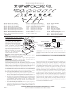
OUTFITTERS SERIES
Model Numbers
ES-100, ES-200, ES-300
MS-100, MS-200, MS-300
(9,000 Btu per Burner)
ES-S100, ES-S200, ES-S300
SE-200, SE-300
(10,000 Btu per Burner)
1/4" HEX
FLANGE NUT
1/4" BOLT
GRATE
TOP
BURNER
VALVE
KNOB
BODY
LEG
Model No.
SE-200 w/SLK-28