


12427-2-0903
Page 8
Attention! If one of the above procedures results in pressures in excess
of 1/2 psig (14" w.c.) (3.5 kPa) on the appliance gas valve, it will result
in a hazardous condition.
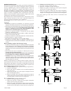
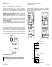
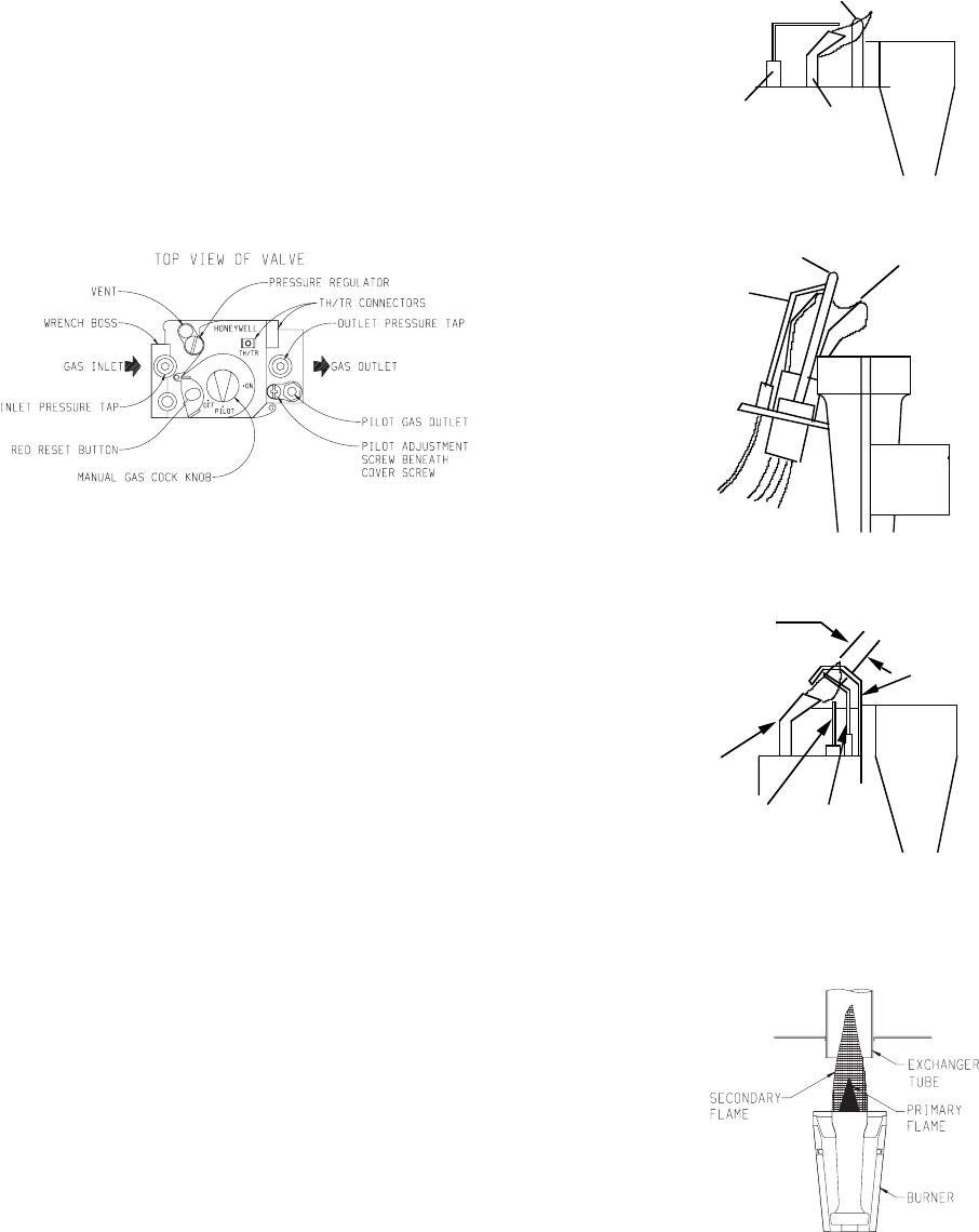
Checking Manifold Pressure
Both Propane and Natural gas valves have a built-in pressure regulator
in the gas valve. Natural gas models will have a manifold pressure of
approximately 4.0" w.c. (.996kPa) at the valve outlet with the inlet
pressure to the valve from a minimum of 5.0" w.c. (1.24kPa) for the
purpose of input adjustment to a maximum of 10.5" w.c. (2.615kPa).
Propane gas models will have a manifold pressure approximately 10.0"
w.c. (2.49kPa) at the valve outlet with the inlet pressure to the valve from
a minimum of 11.0" w.c. (2.739kPa) for the purpose of input adjustment
to a maximum of 13.0" w.c. (3.237kPa).
A 1/8" (3mm) N.P.T. plugged tapping, accessible for test gauge
connection, is located on the outlet side of the gas control.
The built-in regulator comes on at approximately 1/4th pressure and full
on in 10 seconds.
Figure 9
High Altitudes
For altitudes/elevations above 2,000 feet (610m), input ratings should
be reduced at the rate of 4 percent for each 1,000 feet (305m) above sea
level. For Canadian high altitude applications, this appliance is suitable
for installation at elevations between 0 feet (0m) and 4,500 feet (1,372m)
without change.
Piezo Pilot Ignitor Instructions
Depressing the red button completely causes a spark to occur at the pilot.
This is a substitute for a match which requires opening the pilot hole
cover.
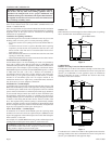
To light the pilot, it is important that the electrode be 1/8" (3mm) from
the thermocouple. The spark must occur at the point the burner flame
hits the thermocouple. The end of the electrode will be red hot with the
pilot on.
On a new installation with air in the gas line, it is suggested that a match
be used. The match will light the pilot faster than the piezo under this
condition.
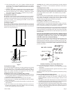
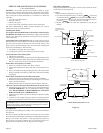
Proper Pilot Flame
The correct pilot flame (Figure 10) will be blue, extending past the
thermocouple. The flame will surround the thermocouple just below the
tip.
Natural gas pilots require adjusting when the inlet gas pressure is above
5" w.c. (1.245kPa). Remove the pilot cover screw on the control valve
(Figure 9), and turn the adjustment screw clockwise to reduce flame.
Replace pilot cover screw to eliminate gas leakage.
LP gas (propane) will not require adjustment.
After use, cleaning may be required for the proper flame.
Proper Main Burner Flame
The correct flame will be a short, blue inner flame with a much larger,
light blue, outer flame. The burner does not have a primary air adjustment.
The flame will be correct if the factory-set pressure and orifice opening
are used. After the furnace has been operating, the burner ports may be
blocked by foreign matter carried in by combustion air. Therefore,
cleaning of the burner may be needed for proper flame.
To clean burner port disconnect the gas supply to the valve, and remove
the screws fastening the burner door. After removing the burner door
from the burner box, remove each main burner. Pilot mounting bracket
will need to be unscrewed and moved out of the way to remove all
burners. Burners can be blown out using compressed air or by blowing
through them. Be sure there is no lint or foreign debris blocking the
burner ports. Reassemble using the same screws earlier removed and
locate pilot in the same position as before and noted above.
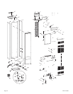
SPARK
ELECTRODE
THERMOCOUPLE
PILOT
BURNER
STANDING PILOT
PILOT LOCATION END VIEW
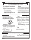
PILOT SHIELD
THERMOCOUPLE
SPARK
ELECTRODE
STANDING PILOT SHOWN
BURNER
PILOT
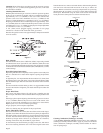
HOT SURFACE
IGNITOR
FLAME
ROD
GROUND
ELECTRODE
3/8" TO 1/2"
PILOT FLAME
IP-MODEL PILOT
Figure 10
Figure 11
Cleaning Combustion (Exchanger) Assembly
A QUALIFIED SERVICE PERSON should remove the combustion
(exchanger) assembly and flue baffles. Apply air pressure to the inside
of the combustion (exchanger) assembly and flue baffles in order to
clear all passageways.