


12427-2-0903
Page 7
8. Align clearance holes on 6" x 10" (152mm x 254mm) duct with
screw holes on inner casing back and mark duct to be 2 1/4" (57mm)
shorter than 8" x 12" (203mm x 305mm) boot. Remove duct and cut
to proper length.
9. Attach 6" x 10" (152mm x 254mm) duct to inner casing back with (4)
#8 x 3/8" (9mm)screws removed in Step 3, 2 on top and 2 on bottom.
10. Insert rear register into 8" x 12" (203mm x 305mm) boot. Attach
rear register to wall with (2) #10 x 1"(25mm) screws provided.
11. Installation of ROK-1 is completed.
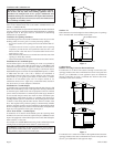
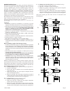
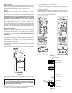
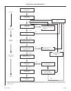
Locating Furnace On Wall
The furnace is to be located on a wall. The furnace is 14 1/8" (35.9cm)
in width and can be recessed into the wall with typical stud spacing.
A template is provided in furnace carton for locating gas line connection.
Also, refer to Figure 7 for positioning the furnace on wall and for
locating gas line connection.
Locating Gas Supply
The gas line can enter the furnace either through the floor or wall. The
gas line opening should be made at this time. Location of the opening
will be determined by the position of floor joists and the valve and union
used for servicing. See Figure 7.
72 3/4"
14 3/8"
CUT OUT OPENING FOR RECESSED MOUNTING
RECESSED MOUNTING
LOCATION
8"
4"
4"
2 1/8"
GAS LINE
HOLE 1 1/4"
ELECTRICAL WIRING HOLE
GAS LINE/ELECTRICAL OPENINGS FOR
RECESSED AND SURFACE MOUNT
Figure 7
Locating Electric Supply
A 7/8" (22mm) diameter knockout is provided at the bottom of the left
and right side panels. A three-prong (grounding) plug assembly is
located within the control compartment (bottom) of the furnace. Please
remove 7/8" (22mm) knockout from appropriate side panel when
routing plug assembly to an electrical outlet.
Installation of Three-prong (Grounding) Plug Assembly
1. Disconnect nylon cap on 3' (914mm) plug assembly from nylon plug
on wiring harness. Remove 3' (914mm) plug assembly from control
compartment (bottom) of the furnace.
2. Remove 7/8" (22mm) knockout from appropriate side panel.
3. Insert nylon cap on 3' (914mm) plug assembly into the 7/8" (22mm)
hole in the side panel.
4. Connect nylon cap on 3' (914mm) plug assembly to nylon plug on the
wiring harness.
5. Place 7/8" (22mm) strain relief bushing around the cord of the 3'
(914mm) plug assembly. Insert 7/8" (22mm) strain relief bushing
into the 7/8" (22mm) hole in the side panel.
Attention! The 7/8" (22mm) strain relief bushing is located within the
same yellow envelope as the Installation Instructions and Owner's
Manual.
Attaching Furnace to Wall
When attaching furnace to the wall remove that portion of baseboard and
molding on the wall which is behind the furnace. Attach furnace to wall,
at the outer casing top, with (2) toggle bolts provided and to floor, at the
outer casing bottom, with (2) #10 x 1 1/2" (38mm) screws provided.
Gas Supply
Check all local codes for requirements, especially for the size and type
of gas supply line required. On Natural gas lines less than 75' (22.9m)
long, use 1/2" (13mm) pipe; on longer runs, use 3/4" (19mm) iron pipe
or equal. On LP gas lines please consult LP gas supplier.
Installing a New Main Gas Cock
Each appliance should have its own manual gas cock.
A manual main gas cock should be located in the vicinity of the unit.
Where none exists, or where its size or location is not adequate, contact
your local authorized installer for installation or relocation.
Compounds used on threaded joints of gas piping shall be resistant to the
action of liquefied petroleum gases. The gas lines must be checked for
leaks by the installer. This should be done with a soap solution watching
for bubbles on all exposed connections, and if unexposed, a pressure test
should be made.
Never use an exposed flame to check for leaks. Appliance must be
disconnected from piping at inlet of control valve and pipe capped
or plugged for pressure test. Never pressure test with appliance
connected; control valve will sustain damage!
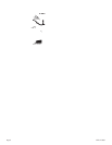
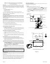
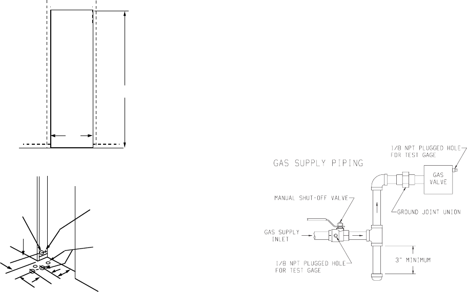
A gas valve and ground joint union should be installed in the gas line
upstream of the gas control to aid in servicing. It is required by the
National Fuel Gas Code that a drip line be installed near the gas inlet.
This should consist of a vertical length of pipe tee connected into the gas
line that is capped on the bottom in which condensation and foreign
particles may collect.
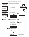
Figure 8
Method of Installing a Tee Fitting Sediment Trap
The use of the following gas connectors is recommended:
— ANS Z21.24 Appliance Connectors of Corrugated Metal Tubing
and Fittings
— ANS Z21.45 Assembled Flexible Appliance Connectors of Other
Than All-Metal Construction
The above connectors may be used if acceptable by the authority having
jurisdiction.
Pressure Testing of the Gas Supply System
1. To check the inlet pressure to the gas valve, a 1/8" (3mm) N.P.T.
plugged tapping, accessible for test gauge connection, must be
placed immediately upstream of the gas supply connection to the
appliance.
2. The appliance and its individual shutoff valve must be disconnected
from the gas supply piping system during any pressure testing of that
system at test pressures in excess of 1/2 psig (3.5 kPa).
3. The appliance must be isolated from the gas supply piping system by
closing its individual manual shutoff valve during any pressure
testing of the gas supply piping system at test pressures equal to or
less than 1/2 psig (3.5 kPa).