


12427-2-0903
Page 14
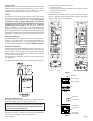
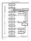
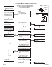
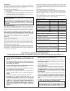
SmartValve™ System Troubleshooting Sequence
Note: Before Troubleshooting, Become Familiar
with the Sequence of Operation
IP SYSTEM TROUBLESHOOTING SEQUENCE
NO
NO
NO
YES
YES
NO
• Turn OFF Gas Supply
• Disconnect System Control
Harness
• Set Thermostat to Call for
Heat
Plug Harness into SmartValve
Control
Wait for Internal Check Delay
(SV9501)
Igniter Warms UP and
Glows Red
System is Okay
Main Valve Opens and
Main Burner Lights
• Turn On Gas Supply
• Pilot Burner Lights
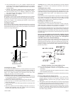
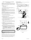
Check for Proper Voltage at
Control Harness (See Inset A
-Voltage Should be 24V
Between Thermostat and
24V Common, and 24V
Between 24V Common and
24V Hot.)
Reconnect Pilot Burner Cable
• Check that Pilot Gas is Flowing
Wait to Assure Pilot Gas Tubing
is Purged.
Replace Igniter/Flame Rod Assembly
Note: Igniter Will Cycle OFF
and Back ON Once During
the 90 Second Ignition Trial
Cycle Thermostat OFF and Back ON
Main Burner Lights
Replace SmartValve Control
Check Transformer and Line
Volt Supply
• Check that Pilot Flame Makes Good
Contact with Pilot Burner Flame
Rod
• Check for Good Electrical
Connection Through the Pilot
Tubing
• If Both of the Above are Good,
Replace Igniter/Flame Rod
• Measure Voltage Between 24V Hot
and 24V Common Leads to
SmartValve Control. Must Measure
at Least 19.5 VAC with Igniter
Powered. See Inset A to Identify
Proper Lead. This Check Must be
Done with the SmartValve Control
Connected and Igniter Powered.
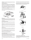
Unplug Pilot Burner Cable.
Measure Voltage at SmartValue
HSI Element Output (See Inset B)
24V Nominal
YES
NO
NO
NO
NO
YES
YES
YES
YES
CHECK
• Line Voltage Power
• Low Voltage Transformer
• Limit Controller
• Thermostat
• Wiring
Replace SmartValve Control
Replace SmartValve Control
START
Replace Igniter/Flame Rod Assembly
Reconnect Pilot Burner Cable
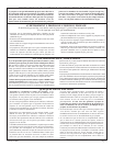
INSET A
24Volt
Thermostat
24
Volts
24 Volt
Common
24
Volts
24 Volt
Hot
EFT
Output
End View
of Control
Harness
Connector
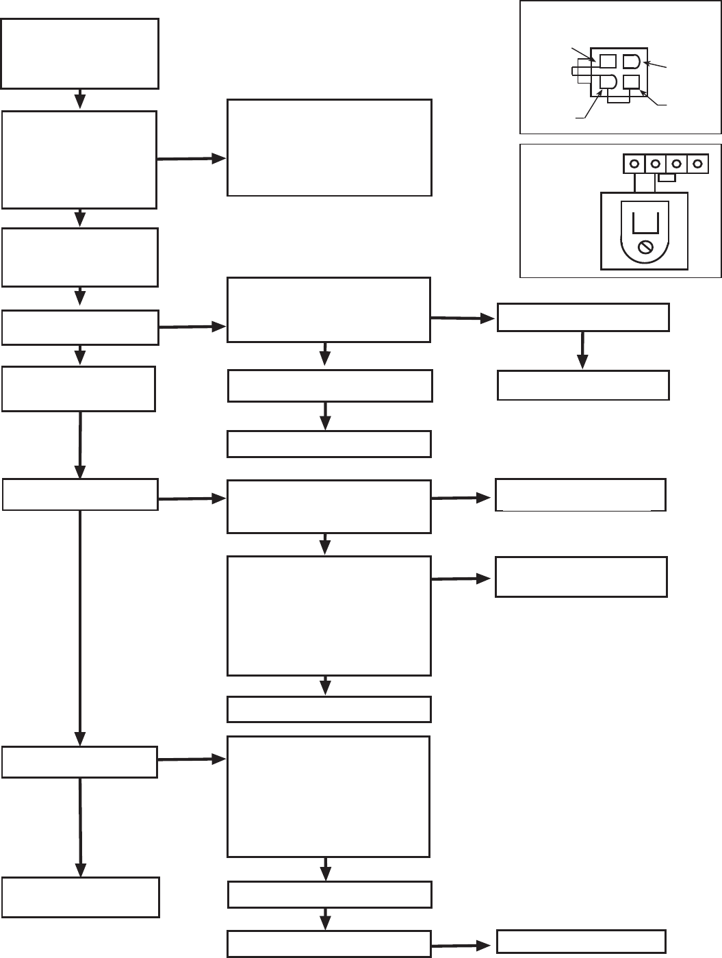
INSET B
HSI
Terminals