


12428-3-0706Page 7
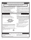
To light the pilot, it is important that the electrode be 1/8” (3mm) from
the thermocouple. The spark must occur at the point the burner flame
hits the thermocouple. The end of the electrode will be red hot with the
pilot on.
On a new installation with air in the gas line, it is suggested that a match
be used. The match will light the pilot faster than the piezo under this
condition.
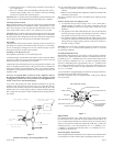
Proper Pilot Flame
The correct pilot flame (Figure 6) will be blue, extending past the thermo
-
couple. The flame will surround the thermocouple just below the tip.
Natural gas pilots require adjusting when the inlet gas pressure is above
5” w.c. (1.245kPa). Remove the pilot cover screw on the control valve
(Figure 5), and turn the adjustment screw clockwise to reduce flame. Re
-
place pilot cover screw to eliminate gas leakage.
LP gas (propane) will not require adjustment.
After use, cleaning may be required for the proper flame.
PROPER FLAME ADJUSTMENT
Figure 6
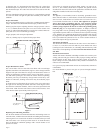
Proper Main Burner Flame
The correct flame will be a short blue inner flame with a much larger
light blue outer flame. The main burner (Figure 7) shows the approximate
height of each part of the flame for each gas. The burner does not have a
primary air adjustment. The flame will be correct if the factory-set pres-
sure and orifice opening are used. After the furnace has been operating,
the burner ports may be blocked by foreign matter carried in by com
-
bustion air. Therefore, cleaning of the burner may be needed for proper
flame.
To clean burner port disconnect the gas supply to the valve, and remove
the eight screws fastening the burner door. After removing the burner
door from the combustion chamber, remove rear burner, pilot burner and
front burner. With front and rear burners removed from furnace, force
water into the ribbon ports and dry with air pressure.
Figure 7
Replacing Fan and Oiling the Motor
The fan motor should be cleaned and oiled once each heating season. To
reach the motor, withdraw the metal shroud surrounding the fan blade by
removing the screws on each side. Oil holes are located on the top at each
end of the motor. Use a few drops of #10 motor oil. To clean the motor,
blow air through its ventilation openings with a vacuum cleaner or low
pressure air source.
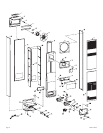
If fan motor is replaced, the silicone rubber gaskets, see Page 10, In
-
dex No. 5, Part 712059, should also be replaced. The gaskets must be
stretched to fit the motor bolts into the gasket holes and then the motor
and gaskets installed on the motor mounting bars.
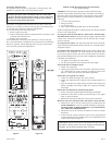
Wiring
The appliance, when installed, must be electrically grounded in accor-
dance with local codes or, in the absence of local codes with the
National
Electrical Code, ANSI/NFPA70 or Canadian Electrical Code CSA C22.1,
if an external electrical source is utilized. This appliance is equipped
with a three-prong (grounding) plug for your protection against
shock hazard and should be plugged directly into a properly ground
-
ed three-prong receptacle. Do not cut or remove the grounding prong
from this plug. For an ungrounded receptacle, an adapter, which has
two prongs and a wire for grounding, can be purchased, plugged into the
ungrounded receptacle and its wire connected to the receptacle mounting
screw. With this wire completing the ground, the appliance cord plug can
be plugged into the adapter and be electrically grounded. A 7/8” (22mm)
hole is provided in the junction box for use with a conduit connector if
local codes require this type of protection.
Thermostat Installation
The thermostat should be installed in the same room as the furnace 4’
(1.2m) to 5’ (1.5m) above the floor and away from another heat source
(cooking stove, hot water heater, etc.) including walls and doorways with
a heat source in an adjoining room. Do Not Install Thermostat on Out-
side Wall.
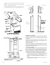
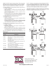
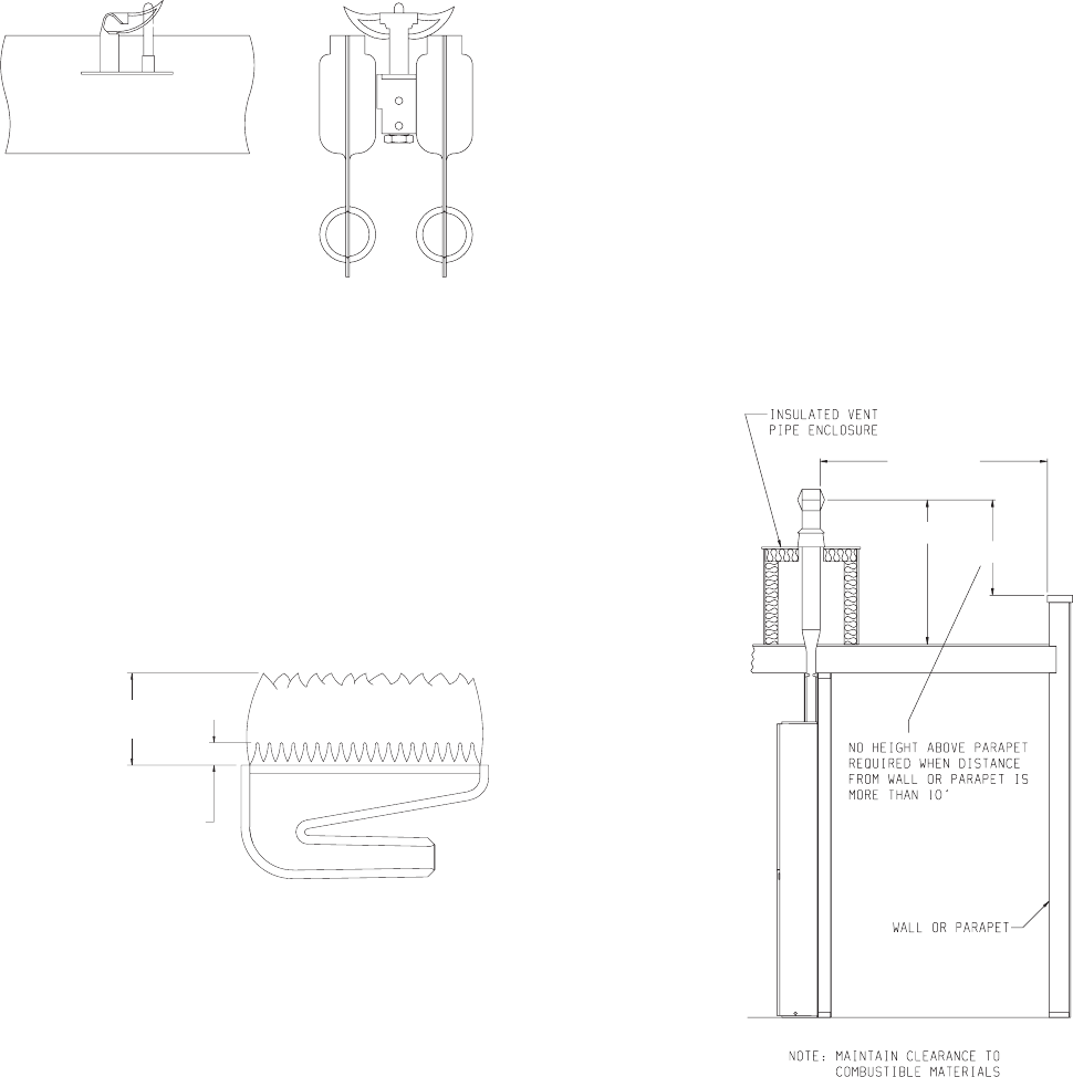
Insulated Vent Enclosure
Vented wall furnaces installed in buildings with flat roofs can have poor
venting. The cold vent pipe will have a delay in proper venting and cause
the wall furnace to shut “OFF” by the vent safety switch. To prevent de-
layed venting as well as condensation of flue products an insulated vent
enclosure is recommended.
Use type B vent pipe and maintain at least one inch (25mm) clearance to
combustibles.
Use metal thimble to protect vent pipe as it passes through combusti
-
bles.
Figure 8
DO MAKE A PERIODIC VISUAL
CHECK OF PILOT & BURNERS
4” (102mm)
6” (152mm)
NAT
AND
LP
1 1/2” (38mm)
1/4” (6mm)
NAT
LP
10’(3m) OR
LESS
3’ (.9m) MIN
2’ (.6m) MIN