


12428-3-0706 Page 6
4. Connect nylon cap on 3’ (914mm) plug assembly to nylon plug on
the wiring harness.
5. Place 7/8” (22mm) strain relief bushing around the cord of the 3’
(914mm) plug assembly. Insert 7/8” (22mm) strain relief bushing
into the 7/8” (22mm) hole in the side panel.
Attention! The 7/8” (22mm) strain relief bushing is located within the same
yellow envelope as the Installation Instructions and Owner’s Manual.
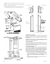
Attaching Furnace to Wall
When attaching furnace to the wall remove that portion of baseboard and
molding on the wall which is behind the furnace. Attach furnace to wall,
at the outer casing top, with (2) toggle bolts provided and to floor, at the
outer casing bottom, with (2) #10 x 1 1/2” (38mm) screws provided.
Attention! The screw holes on the outer casing bottom are off-set above the
floor approximately 3/8” (9.5mm). Do not over-tighten screws and distort
the off-set on the outer casing bottom. Distortion of the outer casing bottom
will not allow the lower front panel to be attached to the furnace.
Gas Supply
Check all local codes for requirements, especially for the size and type of
gas supply line required. On Natural gas lines less than 15’ (4.5m) long,
us (1/2” (13mm) pipe; on longer runs, use 3/4” (19mm) iron pipe or equal.
On LP gas lines please consult LP gas supplier.
Installing a New Main Gas Cock
Each appliance should have its own manual gas cock.
A manual main gas cock should be located in the vicinity of the unit. Where
none exists, or where its size or location is not adequate, contact your local
authorized installer for installation or relocation.
Compounds used on threaded joints of gas piping shall be resistant to the
action of liquefied petroleum gases. The gas lines must be checked for
leaks by the installer. This should be done with a soap solution watching
for bubbles on all exposed connections, and if unexposed, a pressure test
should be made.
Never use an exposed flame to check for leaks. Appliance must be
disconnected from piping at inlet of control valve and pipe capped
or plugged for pressure test. Never pressure test with appliance con-
nected; control valve will sustain damage!
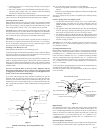
A gas valve and ground joint union should be installed in the gas line
upstream of the gas control to aid in servicing. It is required by the Na
-
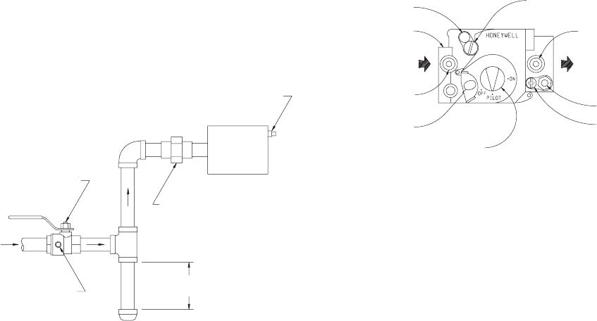
tional Fuel Gas Code that a drip line be installed near the gas inlet. This
should consist of a vertical length of pipe tee connected into the gas line
that is capped on the bottom in which condensation and foreign particles
may collect.
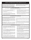
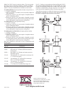
Figure 4
Method of Installing a Tee Fitting Sediment Trap
The use of the following gas connectors is recommended:
–ANS Z21.24 Appliance Connectors of Corrugate Metal Tubing and
Fittings
–ANS Z21.45 Assembled Flexible Appliance Connectors of Other Than
All-Metal Constructions
The above connectors may be used if acceptable by the authority having
jurisdiction.
Pressure Testing of the Gas Supply System
1. To check the inlet pressure to the gas valve, a 1/8” (3mm) N.P.T.
plugged tapping, accessible for test gauge connection, must be
placed immediately upstream of the gas supply connection to the
appliance.
2. The appliance and is individual shutoff valve must be disconnected
from the gas supply piping system during any pressure testing of
that system at test pressures in excess of 1/2 psig (3.5 kPa).
3. The appliance must be isolated from the gas supply piping system
by closing its individual manual shutoff valve during any pressure
testing of the gas supply piping system at test pressures equal to or
less than 1/2 psig (3.5 kPa).
Attention! If one of the above procedures results in pressures in excess
of 1/2 psig (14” w.c.) (3.5 kPa) on the appliance gas valve, it will result
in a hazardous condition.
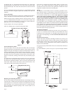
Checking Manifold Pressure
Both Propane and Natural gas valves have a built-in pressure regulator
in the gas valve. Natural gas models will have a manifold pressure of ap
-
proximately 4.0” w.c. (.996kPa) at the valve outlet with the inlet pressure
to the valve from a minimum of 5.0” w.c. (1.24kPa). Propane gas models
will have a manifold pressure approximately 10.0” w.c. (2.49kPa) at the
valve outlet with the inlet pressure to the valve from a minimum of 11.0”
w.c. (2.739kPa) for the purpose of input adjustment to a maximum of
13.0” w.c. (3.237kPa).
A 1/8” (3mm) N.P.T. plugged tapping, accessible for test gauge connection,
is located on the outlet side of the gas control.
The built-in regulator comes on at approximately 1/4th pressure and full
on in 10 seconds.
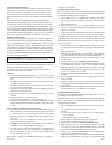
Figure 5
High Altitudes
For altitudes/elevations above 2,000 feet (610m), input ratings should
be reduced at the rate of 4 percent for each 1,000 feet (305m) above sea
level. Canadian High Altitudes for locations having an elevation above
mean sea level between 2,000 feet (610m) and 4,500 feet (1370m), the
manifold pressure is to be decreased from 4.0” w.c. (.996kPa) to 3.2”
(.797kPa) w.c. for Natural Gas and from 10.0” w.c. (2.49kPa) to 8.0” w.c.
(1.992kPa) for Propane Gas.
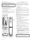
Piezo Pilot Ignitor Instructions
Depressing the red button completely causes a spark to occur at the pilot. This
is a substitute for a match which requires opening the pilot hole cover.
GAS SUPPLY PIPING
1/8(3mm)NPT PLUGGED HOLE
FOR TEST GAGE
GROUND JOINT UNION
3”(76mm)MINIMUM
MANUAL SHUT-OFF VALVE
GAS SUPPLY
INLET
1/8 (3mm) NPT PLUGGED HOLE
FOR TEST GAGE
GAS
VALVE
TOP VIEW OF VALVE
PRESSURE REGULATOR
OUTLET PRESSURE TA
P
GAS
OUTLET
PILOT GAS OUTLET
PILOTADJUSTMENT
SCREW BENEATH
COVER SCREW
MANUAL GAS COCK KNOB
RED RESET BUTTON
INLET PRESSURE TA
P
GAS INLET
WRENCH BOSS
VENT