


19563-1-0706 Page 11
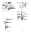
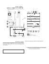
Venting (Figures 7 and 8)
This unit is vented directly out the back using the concentric vent
tube assembly provided. See Figure 2 for vent hole location. This
hole location can be conveniently moved closer to unit exhaust
outlet tube to avoid wall stud interference if necessary. The orange
silicone exhaust elbow would need to be cut to length. Do not locate
vent directly behind the exhaust outlet.
The vent provided will accommodate walls up to 10" thick and
can be cut shorter for thinner walls if desired by using a hacksaw
or cut-off saw. Be sure to leave the minimum 3/4" of tube length
extending beyond the outside wall plate. Both the inner and outer
tube will be cut to the same length as the inner exhaust tube has an
extension piece which is added during final outside assembly.
Be sure to deburr the ends with a file after cutting. Installation is
easy after cutting the wall opening secure the vent terminal box
in place using the (4) 10 x 1" hex-head screws provided. Locate
the box so that the middle exhaust tube is directed toward the
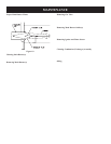
furnace exhaust outlet opening. See Figure 8. Attach the black 2"
flexible inlet air hose to the bottom 2" connector on the vent box
using a hose clamp. Secure the other end to the lower inlet air
box connector using the hose clamp. Do not kink hose. Attach the
long straight end of the 2" orange silicone exhaust elbow to the
middle vent terminal tube and rotate the elbow toward the furnace
exhaust outlet. Secure the hose to the vent box using a hose clamp.
Carefully push the furnace back closer to the wall and secure the
exhaust elbow to the 2" exhaust tube exiting the unit. Secure the
elbow in place using the last remaining hose clamp. The furnace
can now be secured to the wall.
For wall depths thicker than 10" (254mm) order the extended vent
terminal kit which will cover walls to 32" (813mm) thickness.
The vent pipes must be cut to length to assemble for desired
wall thickness. Do not extend venting beyond the 32" maximum
length.
Installation of Shroud
To complete inside installation, secure furnace to the wall bracket
by attaching the two wall mounting brackets to the wall bracket by
using (2) 10 x 1/2" (13mm) hex-head screws provided (See Figures
4 and 6). To attach the right shroud and left shroud to the casing
back, the 3/4" wide flange on the shroud must be positioned toward
the casing side. When positioned correctly, the (6) louvers on the
shroud will be facing up and the knock-out on the shroud will be
facing down. Attach the right shroud and left shroud to the casing
back with (3) 10 x 1/2" hex-head screws supplied in hardware
package, for each shroud. Attach top shroud to right shroud and
left shroud with (4) Phillips-head screws, supplied in hardware
package. Insert air filter into top shroud.
Attention: If the right shroud and left shroud are installed incorrectly,
with the 3/4" wide flanges facing inward, the top shroud will not
be able to be installed onto the side shrouds. The top shroud will
appear to be 2 inches, too narrow.
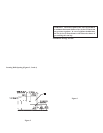
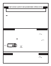
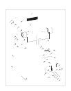
Vent Terminal (Figure 9)
Place the 6 3/8" x 6 3/8" (162mm x 162mm) black foam, wall plate
gasket within the mounting plate. The 4 3/4" (121mm) diameter
hole in the black foam gasket will allow for installation of the
concentric vent tube assembly. Slide the outside mounting plate into
place on the concentric vent tube assembly. The outside mounting
plate should seal against the face of the building and be secured
in place using (4) 10 x 1" hex-head screws. Be sure to caulk and
seal around the pipe on the exterior using high temperature exterior
grade, silicone caulk rated at 204°C/400°F. Wipe some silicone
sealant on the 2" (51mm) exhaust pipe extension. The end cap can
be pushed into place on the exhaust outlet tube.
Attention: The opening on the bottom of the end cap must be
positioned toward the ground. The opening on the bottom cannot
be pivoted to the right or left, it must be centered toward the
ground.
Figure 9
Reassembly and Resealing Vent-Air Intake System
When vent-air intake system is removed for servicing the furnace,
the following steps will assure proper reassembly and resealing
of the vent-air intake assembly. Be sure all hose connections are
re-secured in place using the hose clamps removed. Reattach all
screws securing mounting flanges and inspect all connections for a
tight fit. Use high temperature silicone caulk rated at 204°C/400°F
to reseal the inlet air vent pipe to the mounting plate.
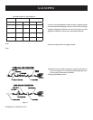
NO.10 X1 1/2"
SCREWS(4)