


13118-7-0408 Page 9
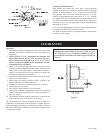
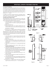
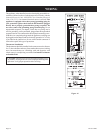
Locating Wall Opening
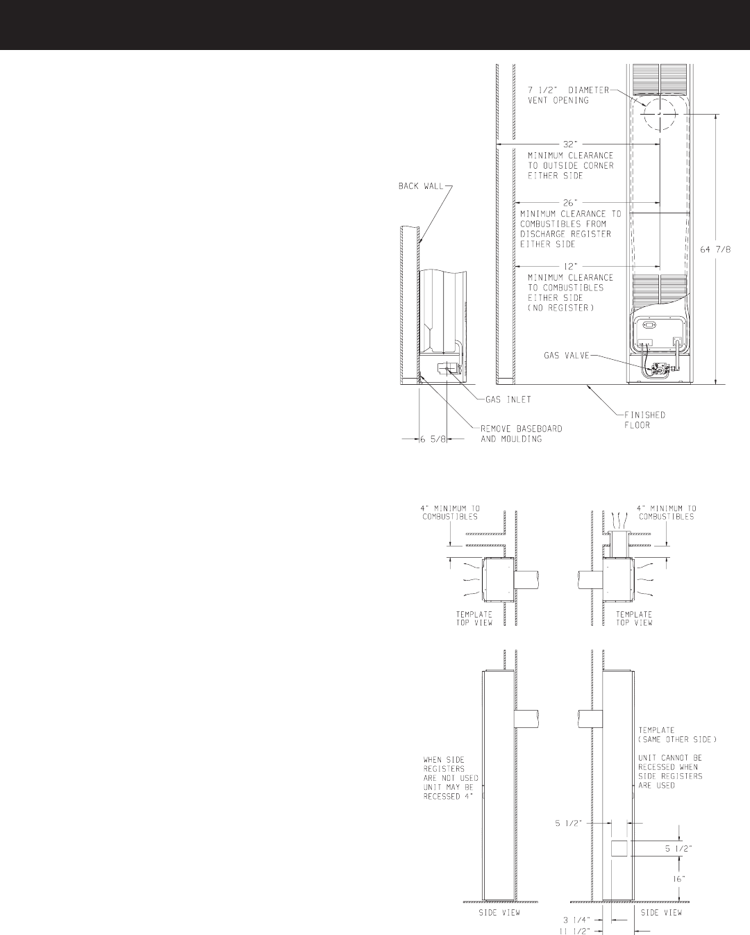
The furnace is to be located on an outside wall. Locate wall studs so
that wall opening will be located between wall studs. The furnace
is 16 inches in width and normal 16 inches on center studs will
not allow the furnace to be recessed into the wall unless a stud is
repositioned. The wall opening required as shown in Figure 5 is a
diameter of 7 1/2 inches.
A template is provided in furnace carton for positioning furnace
on the wall. Also, refer to Figure 5 for positioning the furnace on
wall and for locating gas line connection.
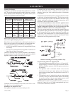
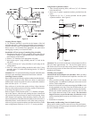
Installing Optional Side Outlets
Side outlet register, SOR-1 may be installed on one or both sides
of the furnace at the required clearances of 18 inches to adjacent
wall or combustible material as shown in Figure 4.
1. Locate and cut the 5 1/2" square opening in the cabinet side
using the template from the kit, exposing the inner liner
knock-out.
2. Remove the knock-out.
3. Place the register on the 5 1/2" opening with the louvers set
for the desired direction and mark the mounting holes using
the register as a template.
4. Drill two (2) 1/8" diameter holes in cabinet side and fasten
the register in place with two (2) 10 x 1" screws provided.
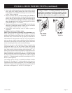
Side outlet kit, 10" boot assembly with register, SOK-1 for warm
air discharge into an adjoining room may be installed on either side
of the furnace at the required clearance of 4 inches to adjacent wall
as shown in Figure 7.
1. Locate and cut the 5 1/2" square opening in the cabinet side
using the template from the kit, exposing the inner liner
knock-out.
2. Remove the knock-out.
3. Using the inner and outer boots as hole templates, mark
and drill eight (8) 1/8" diameter holes in the inner liner and
cabinet side.
4. Using Figure 7 locate and cut a 6 3/4" square opening through
walls.
5. Prepare wall opening for the vent-air intake system (see
Locating Wall Opening).
6. With furnace in place, after checking alignment of side outlet
opening in wall and furnace, place the 9 3/8" x 9 3/8" side
outlet wall plate over outer boot, pass the outer boot through
the wall and attach side outlet wall plate to furnace side of
wall with two (2) 10 x 1" screws provided.
7. Fasten outer boot to the cabinet side with four (4) 8 x 1/4"
screws provided.
8. Position and attach inner boot to inner liner with four (4) 8
x 1/4" screws provided.
9. Locate the register with its louvers positioned for the desired
air discharge direction and mark the mounting holes using
the register as a template.
10. Drill two (2) 1/8" diameter holes in the wall and fasten the
register in place with two (2) 10 x 1" screws provided.
Figure 5
Figure 6 Figure 7
INSTALLATION INSTRUCTIONS