


ii
FIGURES
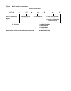
Figure i Model number nomenclature . . . . . . . . . . . . . . . . . . . . . . . . . . . . . . . . . . . . . . . . .Inside Front Cover
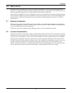
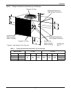
Figure 1 Dimensions, horizontal air discharge . . . . . . . . . . . . . . . . . . . . . . . . . . . . . . . . . . . . . . . . . . . . . . . . 3
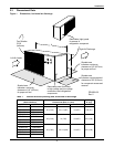
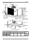
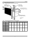
Figure 2 Dimensions, top air discharge . . . . . . . . . . . . . . . . . . . . . . . . . . . . . . . . . . . . . . . . . . . . . . . . . . . . . . 4
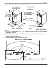
Figure 3 Dimensional data, 277V step-down transformer . . . . . . . . . . . . . . . . . . . . . . . . . . . . . . . . . . . . . . . 5
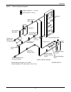
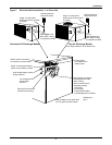
Figure 4 Piping and electrical connections, horizontal discharge. . . . . . . . . . . . . . . . . . . . . . . . . . . . . . . . . . 6
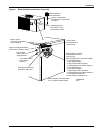
Figure 5 Piping and electrical connections, top air discharge. . . . . . . . . . . . . . . . . . . . . . . . . . . . . . . . . . . . . 7
Figure 6 General piping arrangement . . . . . . . . . . . . . . . . . . . . . . . . . . . . . . . . . . . . . . . . . . . . . . . . . . . . . . . 8
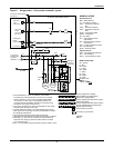
Figure 7 Electrical field connections, 1- to 5-ton units . . . . . . . . . . . . . . . . . . . . . . . . . . . . . . . . . . . . . . . . . . 9
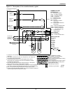
Figure 8 Electrical field connections, 8-ton units. . . . . . . . . . . . . . . . . . . . . . . . . . . . . . . . . . . . . . . . . . . . . . 10
Figure 9 Single-phase, 1-3 ton model schematic, typical. . . . . . . . . . . . . . . . . . . . . . . . . . . . . . . . . . . . . . . . 11
Figure 10 Three-phase, 3-5 ton model schematic, typical . . . . . . . . . . . . . . . . . . . . . . . . . . . . . . . . . . . . . . . . 12
Figure 11 Three-phase, 8 ton model schematic, typical. . . . . . . . . . . . . . . . . . . . . . . . . . . . . . . . . . . . . . . . . . 13
Figure 12 Refrigerant piping diagram . . . . . . . . . . . . . . . . . . . . . . . . . . . . . . . . . . . . . . . . . . . . . . . . . . . . . . . 15
Figure 13 Hot gas bypass diagram . . . . . . . . . . . . . . . . . . . . . . . . . . . . . . . . . . . . . . . . . . . . . . . . . . . . . . . . . . 27
TABLES
Table 1 Cabinet and floor planning data, horizontal air discharge. . . . . . . . . . . . . . . . . . . . . . . . . . . . . . . . 3
Table 2 Electrical and piping connections, top air discharge . . . . . . . . . . . . . . . . . . . . . . . . . . . . . . . . . . . . 4
Table 3 Electrical and piping connections, horizontal air discharge. . . . . . . . . . . . . . . . . . . . . . . . . . . . . . . 6
Table 4 Piping and electrical connections, top air discharge. . . . . . . . . . . . . . . . . . . . . . . . . . . . . . . . . . . . . 7
Table 5 Pipe length and condenser elevation relative to evaporator . . . . . . . . . . . . . . . . . . . . . . . . . . . . . 15
Table 6 Equivalent lengths for various pipe fittings, ft (m). . . . . . . . . . . . . . . . . . . . . . . . . . . . . . . . . . . . . 15
Table 7 Refrigerant charge in Liebert pre-charged R-407C line sets . . . . . . . . . . . . . . . . . . . . . . . . . . . . . 16
Table 8 Liebert PFH unit charge levels and coupling size. . . . . . . . . . . . . . . . . . . . . . . . . . . . . . . . . . . . . . 17
Table 9 Recommended line sizes, OD Cu . . . . . . . . . . . . . . . . . . . . . . . . . . . . . . . . . . . . . . . . . . . . . . . . . . . 17
Table 10 Piping connection sizes and torque . . . . . . . . . . . . . . . . . . . . . . . . . . . . . . . . . . . . . . . . . . . . . . . . . 18
Table 11 Line charges - refrigerant per 100 ft. (30m) of Type L copper tube . . . . . . . . . . . . . . . . . . . . . . . . 18
Table 12 Evaporator Charge Levels . . . . . . . . . . . . . . . . . . . . . . . . . . . . . . . . . . . . . . . . . . . . . . . . . . . . . . . . 20
Table 13 Design refrigerant pressures . . . . . . . . . . . . . . . . . . . . . . . . . . . . . . . . . . . . . . . . . . . . . . . . . . . . . . 21
Table 14 Application limits . . . . . . . . . . . . . . . . . . . . . . . . . . . . . . . . . . . . . . . . . . . . . . . . . . . . . . . . . . . . . . . 21
Table 15 Recommended minimum wire size. . . . . . . . . . . . . . . . . . . . . . . . . . . . . . . . . . . . . . . . . . . . . . . . . . 21
Table 16 Electrical data—Standard sound and ambient models (95°F/35°C) 60Hz . . . . . . . . . . . . . . . . . . 22
Table 17 Electrical data—High ambient models (105°F/41°C) 60Hz . . . . . . . . . . . . . . . . . . . . . . . . . . . . . . 22
Table 18 Electrical data—Quiet-Line models (95°F/35°C) 60Hz . . . . . . . . . . . . . . . . . . . . . . . . . . . . . . . . . 23
Table 19 Electrical data—Standard sound and ambient models (95°F/35°C) 50Hz . . . . . . . . . . . . . . . . . . 23
Table 20 Electrical data—High ambient models (105°F/41°C) 50Hz . . . . . . . . . . . . . . . . . . . . . . . . . . . . . . 23
Table 21 Electrical data - Quiet-Line models (95°F/35°C) 50Hz . . . . . . . . . . . . . . . . . . . . . . . . . . . . . . . . . . 24
Table 22 Field verification charge . . . . . . . . . . . . . . . . . . . . . . . . . . . . . . . . . . . . . . . . . . . . . . . . . . . . . . . . . . 30
Table 23 Troubleshooting. . . . . . . . . . . . . . . . . . . . . . . . . . . . . . . . . . . . . . . . . . . . . . . . . . . . . . . . . . . . . . . . . 31