


Installation
21
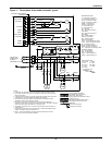
2.6 Electrical Connections
Each unit is shipped from the factory with all internal wiring completed. All power, control wiring
and ground connections must be made in accordance with the National Electrical Code and local
codes. Refer to equipment nameplate regarding wire size and circuit protection requirements. Refer to
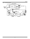
Figures 5, 7 and 8 and electrical schematic (reference Figures 9 through 11) when making connec-
tions. A manual electrical disconnect switch should be installed within 5 feet (1.6 m) of the unit in
accordance with codes.
The three-phase scroll compressor requires proper phasing to ensure correct motor rotation. The com-
ponent connections have been phase synchronized at the factory. Power phasing should be changed
only at the line voltage supply to the unit. To change phasing, switch any two power leads to the unit.
Observe system pressures to determine whether the unit is operating properly.
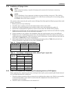
2.6.1 Low-Voltage Control Wire Connections
Field-supplied four-wire control connection (10-wire on 8-ton units) is required between the outdoor
condensing unit and the evaporator. Refer to Figures 5, 7 and 8 and to unit electrical schematic and
Figures 9 through 11.
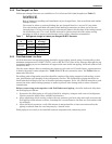
2.6.2 Low-Voltage Control Wire Sizing
Low-voltage wiring should be sized to allow a 1 volt maximum drop due to line resistance between the
evaporator and condensing unit. Use NEC Class 1 or 2 wiring according to wire routing conditions
chosen, local codes and application limits in Tables 14 and 15.
!
WARNING
Use voltmeter to be sure power is turned off before making any electrical connections.
!
CAUTION
Three-phase power must be connected to the unit line voltage terminals in proper sequence so
that scroll compressor rotates in the correct direction.
!
CAUTION
Apply power to condenser 8 hours before operating system. This time is required to allow
liquid refrigerant to be driven out of the compressor. This is especially important at low
ambient temperatures. The compressor crankcase heater is energized as long as power is
supplied to the unit.
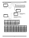
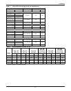
Table 13 Design refrigerant pressures
Suction
53 - 95 PSIG
(365 to 655 kPa)
Discharge
(At Design Ambient)
280 psig (1930 kPa)
High Pressure Cutout 400 psig (2760 kPa)
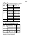
Table 14 Application limits
Input voltage Dry Bulb Air Temperature at Condenser
Minimum Maximum Minimum Maximum
-10%
+10% -30°F (-34°C)
115°F (46°C) Std
Ambient & Quiet-Line
-5% 208/230V
single-phase
125°F (52°C)
High Ambient Models
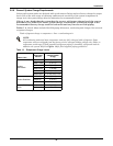
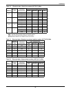
Table 15 Recommended minimum wire size
Max. Distance*
ft. (m)
Min. Wire Gauge
AWG (mm2)
50 (15) 20 (0.75)
100 (30) 18 (1.0)
150 (45) 16 (1.5)
* One-way control wire run between outdoor condensing unit and evaporator.