


Installation
11
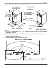
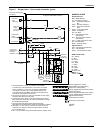
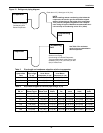
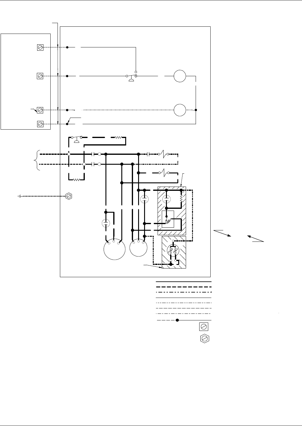
Figure 9 Single-phase, 1-3 ton model schematic, typical
3
2
4
1
C1
HG1
BR
W
BL
1
4
2
3
BK
BK
R
R
R
LLSV
BK
BK
R
'FM'
FAN
MOTOR
2C1
1C1
R
BK
RHTR
BK
BK
RRR BK
BR
Y
Optional on
Selected Units
Supplied on
1-Ton PFC
Models Only
BR
C
R
S
COMP
1
5
2
PR
BDR
C
CSR
A
B
Y
Conductors Field-Supplied
(See Note 5)
HGBP Signal
Output
Connection
EVAPORATOR UNIT
UnitAlarm
Input
Connection
24V Ground
Earth Ground
By Others
1-Phase Line
Voltage Supply
By Others
(See Notes 1 & 3)
OUTDOOR CONDENSING MODULE
See Note 6
HG1
CHTR
BK
BK
BK
BR
CAP2
CAP1
CAP3
BR
L1
L2
HP1
HP2
HGSV
24V Power
Supply
From Unit
Min 40 Va
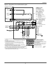
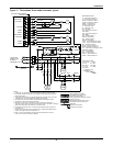
1. All units 208/230V, 1 phase. On 208/230V units installed
in Canada only, CSA requires that L1 and L2 are non-neutral
supply conductors. L1 et L2 pour conducteurs d'alimentation
non-neutres. On other units, L2 is designated neutral. See
unit name plate and installation manual for main supply wiring
information. Use copper conductors only.
2. Use copper conductors only. See unit nameplate for main supply
wire sizing data. Wire per local codes.
3. A remote disconnect switch is to be field-supplied and mounted
within sight of the condensing unit. See unit nameplate for voltage
and amperage requirements.
4. All motors have internal line break overload protectors.
Three-phase motors protected for primary single-phasing conditions.
25,
27
Factory-Supplied Line Voltage
Field-Installed Line Voltage Wiring
Optional Line Voltage Wiring
Factory-Supplied 24V NEC Class 2 Wiring
Optional 24V Wiring
Factory-Supplied 24V NEC Class 2 Wiring
Factory-Supplied Earth Grounding Wire
Pigtail Leads 24V Wiring
Terminal Strip Connection
OR - Orange
R - Red
BR - Brown
P - Purple
GN - Green
Y - Yellow
BL - Blue
BK - Black
W - White
WIRE COLOR CODE
Insulation Color
GN / Y
Tracer Color
191642
Rev. 0
NOMENCLATURE
Standard Devices
BDR -- Bleed Resistor
C1 -- Condenser Contactor
CAP1 -- Compressor Capacitor
Run
CAP2 -- Fan Motor Capacitor
CAP3 -- Compressor Capacitor
Start
CHTR -- Compressor Heater
COMP -- Compressor
FM -- Fan Motor
HP1 -- High Pressure Switch
(Auto Reset)
HP2 -- Pressure Switch Receiver
(Auto Reset)
LLSV -- Liquid Line Solenoid Valve
PR -- Potential Relay
RHTR -- Receiver Heater
Optional Devices
CSR -- Compressor Start Resistor
HG1 -- Hot Gas Relay
HGSV -- Hot Gas Solenoid Valve
5. Terminals 1,2,3, and 4 are for connection of control circuit from
evaporator unit. Wiring by others to be NEC Class 2 and sized
for 1V maximum drop.
6. Wire '1' is connected to the grounded side of the 24V Class 2 circuit.
Grounding Lug Connection