


3
INSTALLATION (cont’d)
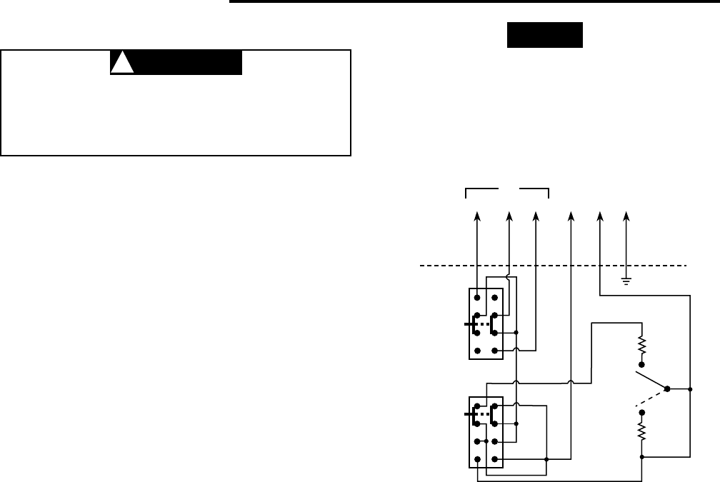
WIRING
To prevent electrical shock and/or equipment
damage, disconnect electric power to system
at main fuse or circuit breaker box until instal-
lation is complete.
Varying the wiring can alter the thermostat/system
operation as shown below:
- For the thermostat to cycle both fan and valve,
connect all wires as shown.
- For the thermostat to cycle fan only (if valve is
not used), do not connect the thermostat orange
wire to the system. Wrap orange lead with approved
electrical tape or wire nut to prevent shorting.
- For the thermostat to cycle the valve only (with
fan on continuously), Connect orange wire to L1
and black wire to VALVE. Connect all other wires as
shown.
NOTE: With the system switch in the OFF position, the
thermostat will prevent both the fan and valve circuits
from turning on.
TAN
BLUE
COOL
COOL
HEAT
HEAT
VALVE
(SOL)
L1*
(HOT)
GNDHIGH
HIGH
FAN
SWITCH
SYSTEM
SWITCH
MED
FAN
MED
OFF
LOW
LOW
RED
BLUE
RED
ORANGE
BLACK
GREEN
1A11-2
5-wire with ground, for single valve,
manual heat/cool changeover
CUSTOMER
CONNECTIONS
Note: Above FAN and SYSTEM switches shown in
MED and HEAT positions respectively.
THERMOSTAT
SCHEMATIC
*L1 is Power In
CAUTION
!
NOTE
This typical wiring diagram shows only the terminal
identification and wiring hookup. Always refer to wiring
instructions, provided by equipment manufacturer, for
system hookup operation.
All wiring should be done according to local and national
electrical codes and ordinances.
The Emerson logo is a
trademark and a service mark
of Emerson Electric Co.