


2
NOTE
SELECT THERMOSTAT LOCATION
Proper location insures that the thermostat will provide
a comfortable home temperature. Observe the follow-
ing general rules when selecting a location:
1. Locate thermostat about 5 ft. above the floor.
2. Install thermostat on a partitioning wall, not on an
outside wall.
3. Never expose thermostat to direct light from lamps,
sun, fireplaces or any temperature radiating equip-
ment.
4. Avoid locations close to windows, adjoining outside
walls, or doors that lead outside.
5. Avoid locations close to air registers or in the direct
path of air from them.
6. Make sure there are no pipes or duct work in that
part of the wall chosen for the thermostat location.
7. Never locate thermostat in a room that is warmer or
cooler than the rest of the home, such as the kitchen.
8. Avoid locations with poor air circulation, such as
behind doors or in alcoves.
9. The living or dining room is normally a good location,
provided there is no cooking range or refrigerator on
opposite side of wall.
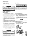
INSTALL THERMOSTAT
To prevent electrical shock and/or equipment
damage, disconnect electric power to system
at main fuse or circuit breaker box until instal-
lation is complete.
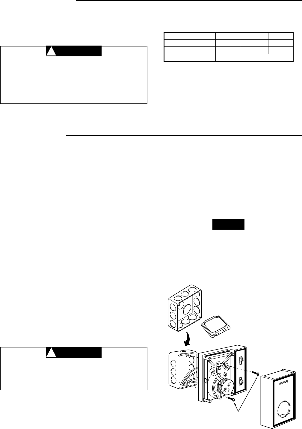
The thermostat may be mounted on a standard 2 x 4
inch vertical outlet box or 2-ganged outlet boxes. When
mounting to a 4 x 4 inch junction box is required, use of
a standard adapter plate (not provided) is necessary.
USE COPPER CONDUCTORS ONLY.
SPECIFICATIONS
Contact Structure: Snap action
Electrical Rating:
Mounting: Standard 2 x 4 inch outlet box or 2-ganged
outlet boxes. Mounting screws are provided with the
thermostat. With a standard adapter plate (not pro-
vided), this thermostat may be mounted on a 4 inch
square junction box
Switch Action: SPDT
(Heating - open on rise)
(Cooling - close on rise)
Temperature Range: 36°F to 90°F (2°C to 32°C)
When the thermostat is set below 40°F (5°C),
damage to the building and/or contents may
result due to freezing. This is possible due to
factory calibration tolerances, thermostat loca-
tion and operating characteristics of the heat-
ing equipment.
System Switch: Heat - Off - Cool
Fan Switch : Low - Medium - High
FAN
S
Y
S
T
E
M
LOW
HEAT
5
0
6
0
W
H
I
T
E
-
R
O
D
G
E
R
S
7
0
8
0
9
0
4
0
40
50
60
70
80
90
4 x 4
JUNCTION
BOX
ADAPTER PLATE
(NOT PROVIDED)
USE 2 x 4 OR 4 x 4
JUNCTION BOX
1A11-2
MOUNTING
SCREWS (2)
VOLTAGE (AC) 120V 240V 277V
Full Load Amps. 5.5 2.75 2.3
Locked Rotor Amps. 33.0 16.5 13.8
Pilot Duty 125VA
CAUTION
!
INSTALLATION
Install the thermostat as follows:
1. Before mounting, connect system wiring to proper
color-coded leads at rear of thermostat. Follow
equipment manufacturer's instructions or refer to
wiring diagram for typical system hookups.
2. Remove thermostat cover by grasping top and bottom
of cover and pull straight out. Dress wiring into junction
box and secure thermostat to outlet box with mounting
screws.
DO NOT PUSH OR DAMAGE THE TEMPERATURE
KNOB DURING INSTALLATION.
3. Install thermostat cover, turn knob to desired set-
ting, and set selector switches for the appropriate
system function and fan speed.
CAUTION
!