


Instruction Leaflet
EI 170/171 Strobe and Vibration Smoke Alarm System, for the deaf and hard of hearing.
Introduction
This leaflet describes the installation of the EI 170 and EI
171 Systems.
Important: Read all instructions before installing. This leaf-
let must be left with the end user after installation.
N.B. If the system is not being used for some time the Con-
trol Panel power switch must be in the off position. This will
prevent the battery from being totally depleted and possibly
damaged.
Do not
turn on until it is fully wired.
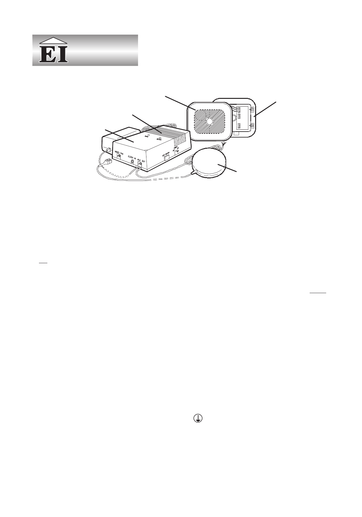
The systems consist of:-
EI 170 System EI 171 System
EI 151 Mains Smoke EI 156 Mains Smoke
Alarm (ionisation) Alarm (optical)
EI 173 Control Panel EI 173 Control Panel
(with built-in strobe) (with built-in strobe)
EI 174 Vibration Pad EI 174 Vibration Pad
EI 172 Pattress (for EI 172 Pattress (for
Smoke Alarm interface) Smoke Alarm interface)
1. Location & Installation
The Control Panel should normally be fixed such that the in
-
ternal strobe light can be seen from the bed and the vibration
pad can be placed under the mattress or pillow. It has to be
powered from the mains (230 VAC) so a suitable power point
or junction box must be available to which it can be perma
-
nently connected. The Smoke Alarm must be located as de
-
scribed in the Smoke Alarm instructions supplied. Cable (10
m) is supplied to connect between the Control Panel and the
EI 172 Pattress for the smoke alarm. This can be extended up
to 50 m (20 ohms max.) with suitable low voltage cable if re
-
quired. The smoke alarm supplied with the system may be in
-
terconnected with other
EI mains powered smoke alarms up
to a maximum of 12 smoke alarms in total. Many dwellings re
-
quire more than one smoke alarm for minimum protection.
See the smoke alarm instruction leaflet for detailed advise on,
interconnection, maintenance etc.
Warning: This mains operated system should be installed
and interconnnected by a qualified electrician in accordance
with the Regulations for Electrical Installations published by
the Institute of Electrical Engineers (UK). Failure to install this
system correctly may exposethe user toshock or fire hazards.
Control Panel
The Control Panel should be permanently fixed to the wall
using the screws and plastic plugs enclosed. The screws
should be spaced 114 mm (4.5 in) vertically apart. The top
screw will be 27 mm (1.1 in) below the top surface of the con-
trol panel when installed. The screws (large heads) should be
screwed into the wall leaving a gap of approximately 4 mm
(0.15 in) under the head. Fit the keyhole slots on the back of
the control panel over the screw heads and slide the panel
down vertically into position.
The mains adaptor can be plugged into a socket. The socket
must not be used for any other equipment and it must always
be switched on.
It is preferable to permanently wire the unit into a mains junc
-
tion box. Wire according to the following instructions.
Warning: First removethe power to the circuitat the distribu
-
tion board. If you are in any doubt about how to do this, get
help from a qualified electrician.
Connecting to mains junction box.
The mains lead wires are colour coded as follows:
brown: live
blue: neutral
The wire whichis coloured blue mustbe connected to theter
-
minal/wire which ismarked with the letterN or coloured black.
The wire which is coloured brown must be connected to the
terminal/wire which ismarked with the letterL or coloured red.
The apparatus is not to be earthed, so no connection is to be
made to terminals or wires marked with the letter E, the sym
-
bol or coloured green or green and yellow.
Bring the low voltage wiring to where the smoke alarm is to
be located. Route all wires neatly and securely along the walls
and ceilings.
Note: Turning off the power switch on the Control Panel
does not switch off the apparatus from the supply mains. The
switch removes the AC and battery power from the Control
1
(or EI 156 - optical)
STROBE
VIBRATION PAD EI 174
AC SMOKE ALARM EI 151 - IONISATION
(With rechargeable battery
for one week standby)
CONTROL PANEL
EI 173
PATTRESS EI 172
Professional
®