


INSTALLATION GUIDE FOR THE ELECTRIC FIREPLACE
LISTINGS AND CODE APPROVALS
The BF series fireplaces have been tested in accordance with the UL 2021and CSA C22.2 No.
46 standards for fixed and location-dedicated electric room heaters.
MODEL SPECIFICATIONS
Model Number Description Voltage Volts
Rated Power Watts
Remote
Control
AMPS
120Volt
BF392SD 39” two sided 120 1500 STANDARD 12.5
NOTE: Power ratings shown include the light bulbs and motor
STEP-BY-STEP INSTALLATION (Note: Please read all instructions before installing)
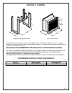
1. Rough in framing opening following the recommended dimensions (Section A:
Framing).
NOTE
Section A: Rough-in framing dimensions are based on ½” thick drywall. Rough-in framing
dimensions will vary for different drywall thicknesses.
2. Allow 8” of service cable for connecting to the junction box on the fireplace. Remove
the outer jacket and strip the individual conductors ½” from the end.
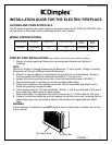
3. Loosen the screw securing junction box cover and remove the cover (FIGURE 1).
4. Remove knockouts if necessary or use the provided cable clamp.
5. Place unit in position in the opening, level with shims if necessary and attach unit to
frame using nailing flanges provided.
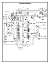
6. Unit is factory wired for 120 volt installation. Wires L1, N & G are attached to the rear of
the junction box cable clamp for easy access.
7. Wire a dedicated, 15 amp fused circuit with three wires (L1, N &G) rated for 120 volts.
8. Place all connectors inside the unit and replace the junction box cover, ensuring that the
cable clamp grips only the jacket of service, thermostat and if applicable wall switch
lines.
WARNING
Ensure method of installation does NOT obscure the air intake slots on bottom front of unit
in any manner.
7205760100REV03
FIGURE 1
1
Junction Box
Air Intake Slots