


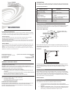
Crestron GLS-LOL
(Wattstopper P/N LS-290C)
PHOTOCELL LIGHT SENSOR
Operations & Installation Guide
FCC Compliance Statement:
Further Inquiries
If you cannot locate specific information or have questions after reviewing this guide, please take
advantage of Crestron's award winning customer service team by calling Crestron at
1-888-CRESTRON [1-888-273-7876].
You can also log onto the online help section of the Crestron website (www.crestron.com/onlinehelp) to
ask questions about Crestron products. First-time users will need to establish a user account to fully
benefit from all available features.
Future Updates
As Crestron improves functions, adds new features and extends the capabilities of the GLS-LOL units,
additional information may be made available as manual updates. These updates are solely electronic
and serve as intermediary supplements prior to the release of a complete technical documentation
revision.
Check the Crestron website periodically for manual update availability and its relevance. Updates are
identified as an “Addendum” in the Download column.
This device complies with part 15 and part 18 of the FCC rules. Operation is subject to the following
two conditions: (1) This device must not cause harmful interference, and (2) This device must accept
any interference received, including interference that may cause undesired operation.
The GLS-LOL is a low voltage photocell which senses light levels and signals this data
to an interface device such as the GLS-SIM connected to the Crestron
®
control system.
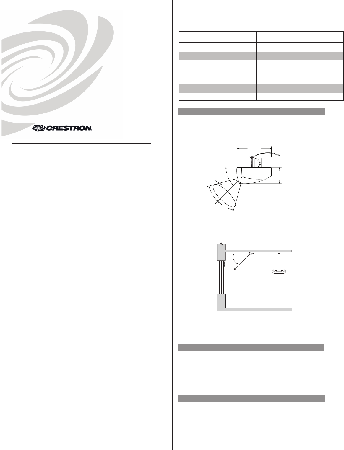
GLS-LOL Specifications
Photocell Placement
The photocell is designed for mounting in a dry location that views daylight. The photocell
should not directly view illumination from an electric light source. The following figure
shows the GLS-LOL field of view.
Where windows are the primary source of daylight, the photocell typically mounts on the
ceiling between the
window and the first row of fixtures. (Refer to the following figure.) The
photocell points toward the window.
For skylight applications, the photocell mounts in the lightwell of the skylight and should
view the incoming daylight. Typically, the photocell is aimed toward the skylight. The light
level range adjustment jumper may need to be changed to 60-6000fc for skylight
applications.
Light Level Testing
Before installing the photocell, verify the daylight levels on a sunny day at the proposed
location of the photocell. With the lights switched off, use a light meter to read the daylight
level. Orient the light meter in the same direction that the photocell will view. The light
levels under sunny conditions must be at least 35fc. If
the light levels are less, you should
select another location or reorient the photocell.
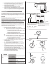
INSTALLATION
Wiring and Testing
Use CRESNET-P/-NP cables only. Maximum distance is 250 feet.
1. To access the GLS-LOL wiring terminals, insert a small, flatblade
screwdriver into a slot on the housing and remove the base from the lens
assembly.
2. Review the “MOUNTING” section on the next page to determine how the
cable to the controller will enter the photocell housing. Modify either the
lens housing or the base as instructed in step 2A or 2B.
DESCRIPTION
• To be installed and/or used in accordance with appropriate electrical codes and
regulations.
• If you are unsure about any part of these instructions, consult a qualified electrician.
• Sensors must be mounted on a vibration free surface.
• All sensors must be mounted at least 6 feet away from air vents.
WARNINGS, CAUTIONS & NOTES
When wiring the Cresnet
®
network, consider the following:
• Use Crestron Certified Wire.
• Use Crestron power supplies for Crestron equipment.
• Provide sufficient power to the system.
NETWORK WIRING
CAUTION: Insufficient power can lead to unpredictable results or damage to the
equipment. Please use the Crestron Power Calculator to help calculate how much power
is needed for the system. (www.crestron.com/calculators).
WARNING: To avoid fire, shock, or death; turn off power at circuit breaker or fuse and
test that power is off before wiring!
NOTES: Observe the following points regarding sensor installation.
PREPARING AND CONNECTING WIRES
Strip the ends of the wires approximately 1/2”. Use care to avoid nicking the conductors.
Twist together the ends of the wires that share a connection and tin the twisted
connection. Apply solder only to the ends of the twisted wires. Avoid tinning too far up
the wires or the end becomes brittle.
Field of View & Mounting
Placement
Peak
Sensitivity
GLS-LOL
Light Fixture
Window
45°
Crestron Electronics, Inc. Operations & Installation Guide-DOC. 6774A
15 Volvo Drive Rockleigh, NJ 07647 (2023057)
Tel: 888.CRESTRON 12.08
Fax: 201.767.7576 Specifications subject to
www.crestron.com change without notice.
SPECIFICATION
DETAILS
Power Consumption
0.2W (8mA @ 24VDC)
Field of View Coverage 60° Cone
Output
Signal Range:
Light Level Range:
0 - 10VDC
Selectable, 3 to 300 footcandles (fc),
30 to 3000fc, 60 to 6000fc
Recommended Mounting Location
Directly above work space
Cable to GLS-SIM or other
compatible Crestron interface
device.
GLS-LOL
Peak
sensitivity
1.2 in.
(3.05 cm)
45º
30º
30º
Ceiling tile or drywall
60º field of view
2.0 in.
(5.08 cm)
UL and cUL Listed
Class 2