


nstallation
....................... ,,,., , u,,..., ,,, , , i .,.,,, i, .
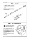
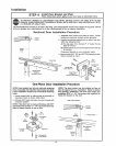
STEP 10 Connect Door Arm to Trolley
Follow only those instructions which apply to your door type°
H,, ,,, ,.,, i,,, ii , i,, , ,m H,,,, ,,, ,t , , i ,
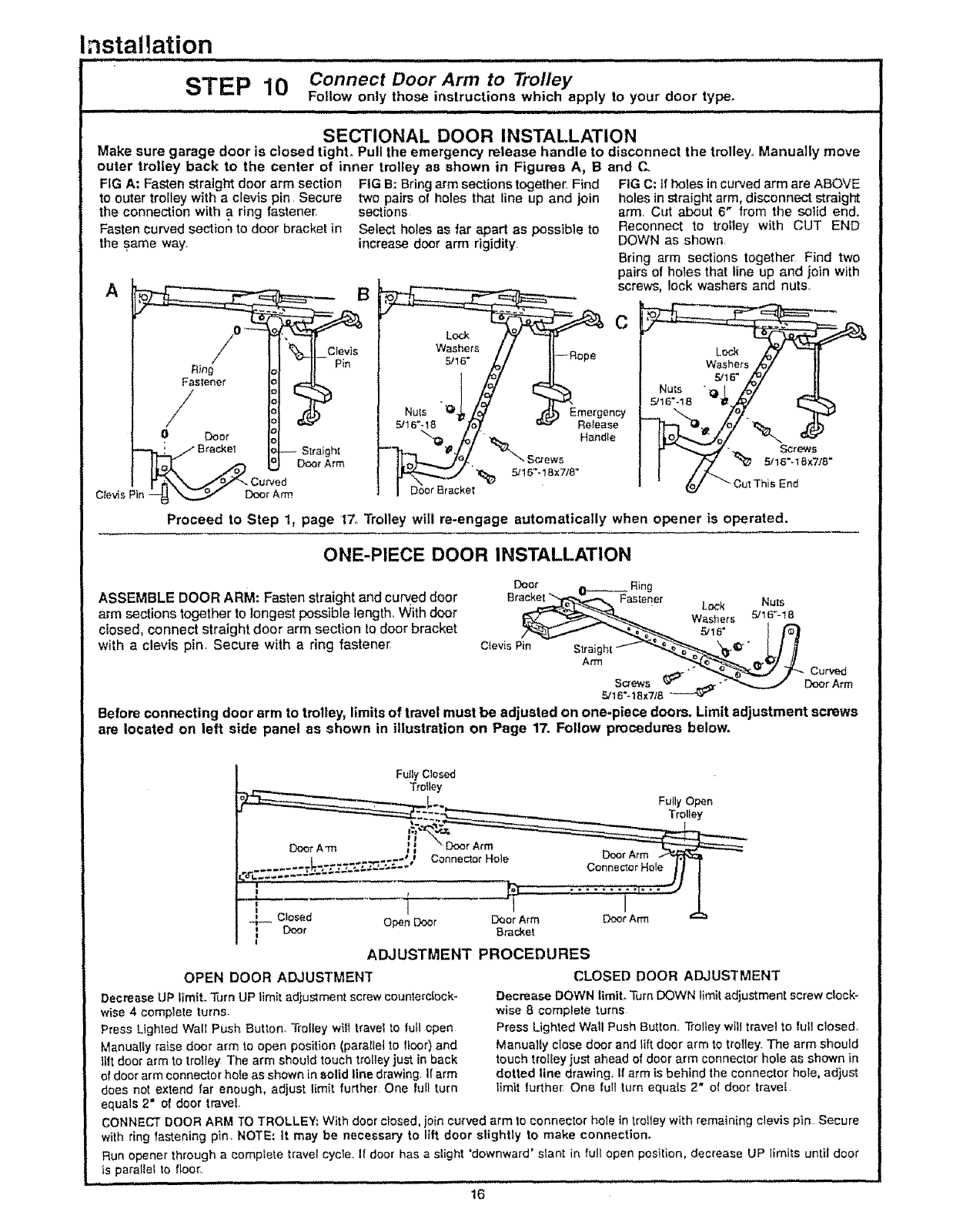
SECTIONAL DOOR INSTALLATION
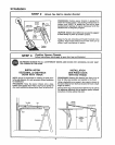
Make sure garage door is closed tighL Pull the emergency release handle to disconnect the trolley.. Manually move
outer trolley back to the center of inner trolley as shown in Figures A, B and C.
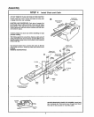
FIG A: Fasten straight door arm section
to outer trolley with a clevis pin. Secure
the connection with a ring fastener.
Fasten curved section to door bracket in
the same way_
A
0 121
--h.._'.F m_et H-- Str_gh_
loL rA,m
1"_"_'X,_.._S°._/_'" Curved
C_evisPin _ _ D_or Arm
FIG B: Bringarm sections together. Find
two pairs of holes that line up and join
sections
Select holes as far apart as possible to
increase door arm rigidity.
FIG C: tf holes incurved arm are ABOVE
holes in straight arm, disconnect straight
arm Cut about 6" from the solid end,
Reconnect to trolley with CUT END
DOWN as shown,
Bring arm sections together, Find two
pairs of holes that line up and join with
screws, lock washers and nuts
Lock
Washers
5/16"
C
Emergency
Reiease
Handle
_t5"-18x_8"
Proceed to Step 1, page 17o Trolley will re-engage automatically when opener is operated.
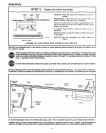
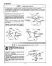
ONE-PIECE DOOR INSTALLATION
ASSEMBLE DOOR ARM: Fasten straight and curved door
arm sections together to longest possible length.. With door
closed, connect straight door arm section to door bracket
with a clevis pin. Secure with a ring fastener,
Door 0-----_ Ring
Bracket _ Fastener - - Nuts
o,o,,o ,o
r,tISc_.ewsz,rt'_.____4_ "" _"___.__ Door Arm
5/16"-18x7/8 "
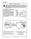
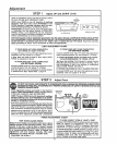
Before connecting door arm to trolley, limits of travel must be adjusted on one-piece doors. Limit adjustment screws
are located on left side panel as shown in illustration on Page 17. Follow procedures below.
Fully Closed
Trolley
Closed Open Doer Deer Arm
Door Bracke[
!
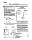
OPEN DOOR ADJUSTMENT
Decrease UP limiL _Jrn UP limit adjustment screw counterclock-
wise 4 complete turns.
Press Lighted Wall Push Button. Trolley will travel to rut1 open
Manually raise door arm to open position (parallel to floor) and
lift door arm to trolley The arm should touch t_olley just in back
of door arm connector hoie as shown in solid line drawing. Ifarm
does not extend far enough, adjust limit further. One lull turn
equals 2" of door travel.
Door Arm
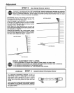
ADJUSTMENT PROCEDURES
CLOSED DOOR ADJUSTMENT
Decrease DOWN limit. Turn DOWN limit adjustment screw clock _
wise 8 complete turns
Press Lighted Wall Push Button. Trolley wilt travel to full closed.
Manualfy close door and lift door arm to trolley. The arm should
touch trolley just ahead of door arm connector hole as shown in
dotted line drawing. If arm is behind the connector hole, adjust
timer furthe_ One full turn equals 2" of door travel
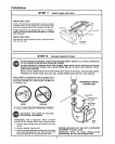
CONNECT DOOR ARM TO TROLLEY: With door closed, join curved arm to connector hole in tro,ey with remaining clevis pin Secure
with ring fastening pin. NOTE: It may be necessary to lift door slightly to make connection.
Run opener through a complete Vavel cycte I! door has a stight 'downward' slant in full open position, decrease UP limits until door
is parallel to floo_
16