


Series 75R Installation Manual, Page 1 of 2
100 Andrews Rd., Hicksville, NY 11801 • Phone: 516-470-1000 • Fax: 516-470-1077 • http://www.neoray-lighting.com
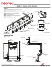
Figure 2
SPACER BLADE
CLEVIS BRACKET
JOINING PLATE
STEEL
HOUSING
ALUMINUM
HOUSING
ALIGNER CLIPS
(SEE DETAIL “B”)
90° OUTSIDE
CORNER
A
B
STEP 1.
Attach housing to
wall angle. Support
housing to structure
with tie-wire.
STEP 2.
Install fixture from
left to right,
beginning with
larger housing to
smaller. Aluminum
housing should be
installed on right
end of the run.
STEP 3.
Join fixture using
joining plates.
STEP 4.
Align fixture using
aligning clips.
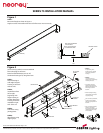
STEP 1.
Mount wall angle as shown in Figure 1.
Angles must be mounted level and true for fixtures to mount correctly
Use tie-wire (by others) to secure and level
fixture housings to structure.
Based on field dimension pre-cut 4 ft
aluminum housing to fit, using hand-saw.
NOTE “A”
Re-positioning clevis
brackets may be required
after cutting aluminum
housings
NOTE “B”
Last housing of run is
aluminum, to be field cut by
installing contractor.
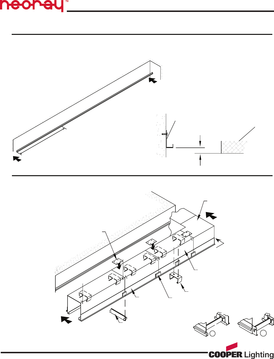
For packing purposes,
aligning clips and spacer
blades are mounted at end
of housing as shown in
detail “A”.
When installing housings,
spacer blades will maintain
a proper opening.
Prior to housing installation,
reposition spacer blades
and aligning clips shown in
detail “B”.
Prior to installing shielding
element, remove and
discard spacer blades for all
shielding elements except
S72 bold bae.
·
·
·
·
·
·
Figure 1
1/4"
FINISHED CEILING
8'(TYPICAL)
WALL ANGLE PROVIDED
IN 8” SECTIONS
CUT LAST SECTION TO
FIT AVAILABLE SPACE
SERIES 75 INSTALLATION MANUAL