


Fixture Type Fitter Type Pole Insert Depth
Medium Epic Spider Mount 4" 6" or Longer
Large Epic Spider Mount 4" 6" or Longer
These instructions do not claim to cover all details or variations in the equipment, procedure, or process described, nor to provide directions for meeting every possible
contingency during installation, operation or maintenance. When additional information is desired to satisfy a problem not covered sufficiently for user’s purpose, please
contact your nearest representative.
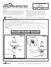
1. Remove Pole Cap and let hang from fitter.
2. Position the service wires to feed through the bottom of the arm. Fig. 1.
3. Slip the arm onto the pole feeding the service wire leads to the interior of the arm. Fig. 2.
4. Connect the service wires lead to the terminal block. Install the Pole Cap and tighten the (3) set screws (provided).
Rotate and position the arm on the pole so the street side and the fixture side are facing the correct direction. The street side
label is located on the inside of the reflector. Fig. 2.
5. Tighten and make sure that locite is applied to the (6) SS set screws (provided) located at the base of the arm. Fig. 2.
6. Pole Application:
WARNING: Do not use fixtures on poles or tennons smaller than noted below. Insure that upper most set screws engage the
tenon/pole.
Customer First Center • 1121 Hwy 74 South • Peachtree City, GA 30269 IMI-654 AVU071135
Epic/Pole Mounted
Fixtures
Sheet 1 of 1
6/18/07 IMI-654
INSTALLATION INSTRUCTIONS
IMPORTANT: Read carefully before installing fixture. Retain for future reference.
General: Upon receipt of fixture thoroughly inspect for any
freight damage, which should be brought to the attention of
the delivery carrier. Compare the catalog description listed
on the packing slip with the fixture label on the housing to
assure you have received the correct merchandise.
Safety: This fixture must be wired in accordance with
the national electrical code and applicable local codes
and ordinance. Proper grounding is required to insure
personal safety. Carefully observe grounding procedure
under installation section. All work should be done by a
qualified electrician.
WARNING:
Risk of Electric Shock. Disconnect power at fuse or circuit breaker before installing
or servicing.
AUXILLIARY
GROUND
TERMINAL BLOCK
SERVICE WIRES
SET SCREWS
POLE CAP
TERMINAL
BLOCK
SERVICE WIRES
FITTER
Fig. 1
Fig. 2