292043-UIM-B-0707
8 Unitary Products Group
LOW VOLTAGE CONTROL CONNECTION
The 24 volt power supply is provided by an internally wired low voltage
transformer which is standard on all models. However, if the unit is con-
nected to a 208 volt power supply the low voltage transformer must be
rewired to the 208 volt tap. See the unit wiring label.
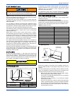
Field supplied low voltage wiring can exit the unit on the top right hand
corner or the right hand side panel (see Fig. 5, item K).
Install a 7/8" plastic bushing in the selected hole and keep low voltage
wiring as short as possible inside the control box.
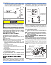
The field wiring is to be connected at the screw terminals of the control
board. Refer to Figure’s 12 and 13.
NOTE: All wiring must comply with local and national electrical code
requirements. Read and heed all unit caution labels.
NOTE: It is possible to vary the amount of electric heat turned on during
the defrost cycle of a heat pump. Standard wiring will only bring on 5
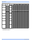
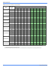
KW of electric heat during defrost see Table 6 and Figures 12 and 13 for
alternate staging.
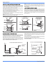
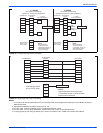
LINE POWER CONNECTIONS
Power may be brought into the unit through the supply air end of the
unit (top when unit is vertical) or the left side panel. Use the hole appro-
priate to the unit's orientation in each installation to bring conduit from
the disconnect. The power lead conduit should be terminated at the
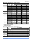
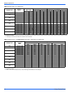
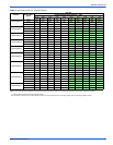
electrical control box. Refer to Tables 4, 8 & 10 for wire requirements.
Also see Figure 10.
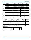
BLOWER SPEED CONNECTIONS
Except for F4FP045, which has a 4-speed motor, and F5FP* which has
a 5-speed high efficiency X-13 motor, all air handlers contain three
speed blower motors which are pre-wired to the control board.
Adjust blower motor speed to provide airflow within the minimum and
maximum limits approved for evaporator coil, electric heat and outdoor
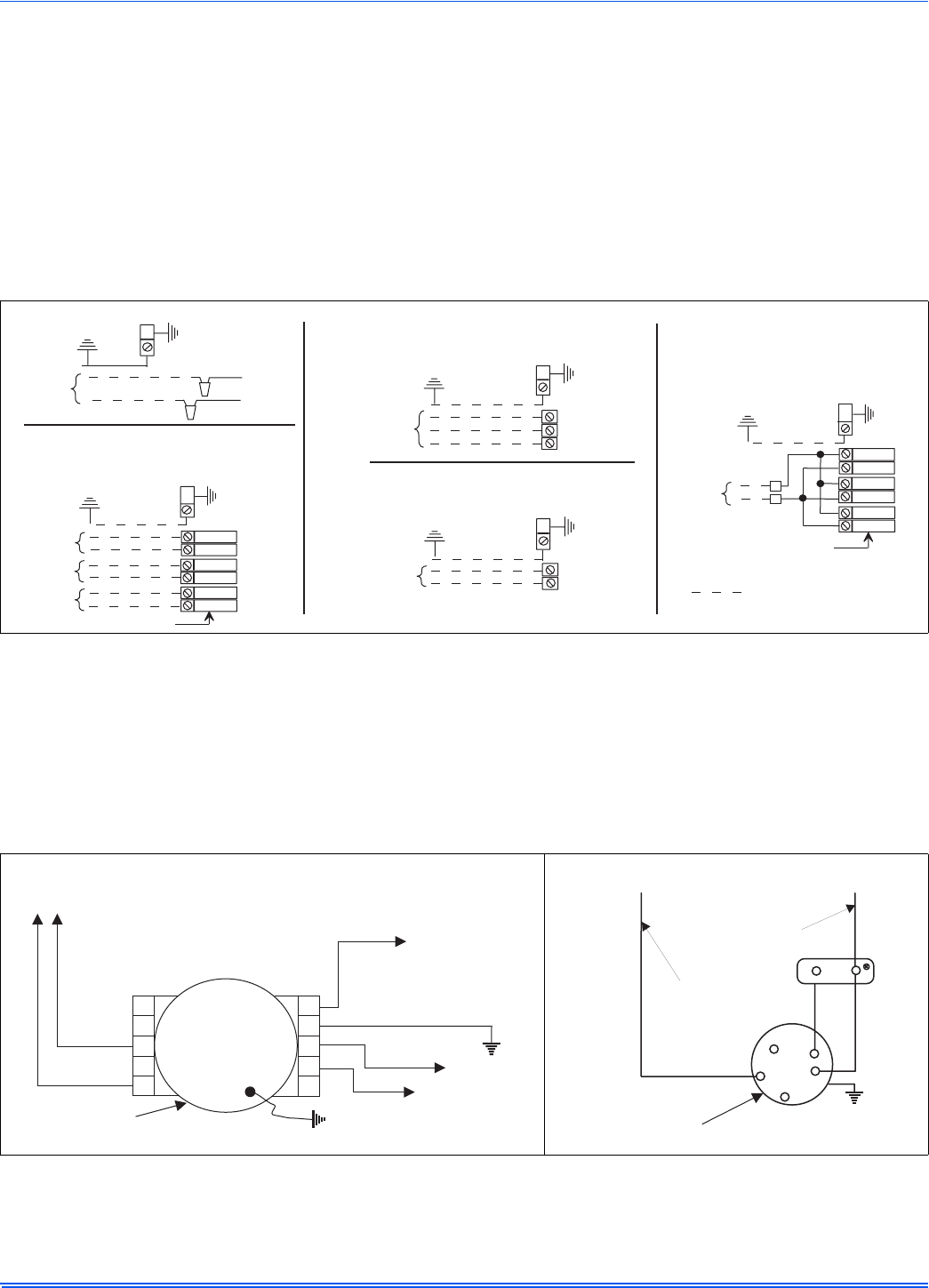
unit. Speed tap adjustments are made at the motor terminal block, See
Figure 11. Airflow data is shown in Tables 6 and 11.
Higher efficiencies will be obtained if the indoor air volume is as high as
possible provided the CFM does not exceed limitations and the sound
level is not objectionable.
Connect motor wires to motor speed tap receptacle for speed desired.
See wiring label for motor wiring details. See Figure 11.
The unit control is designed for the addition of a two speed fan kit. See
accessory kit for details.
FIGURE 10: Line Power Connections
ELECTRIC HEAT
WITHOUT CIRCUIT BREAKER
SINGLE SOURCE (2.5 - 10 KW)
GND. LUG
POWER
SUPPLY
GND.
LUG
ELECTRIC HEAT
WITHOUT CIRCUIT BREAKER
3 PHASE (10 - 15 KW)
GND. LUG
POWER
SUPPLY
GND.
LUG
1 PHASE ELECTRIC HEAT
WITH CIRCUIT BREAKER
AS SHIPPED FROM FACTORY
SINGLE SOURCE
(2.5 - 25 KW) - 25 KW SHOWN
GND. LUG
POWER
SUPPLY
GND.
LUG
1 PHASE ELECTRIC HEAT
WITH CIRCUIT BREAKER
& BREAKER BAR REMOVED
MULTI-SOURCE (15 - 25 KW) - 25 KW SHOWN
GND. LUG
POWER
SUPPLY 1
GND.
LUG
POWER
SUPPLY 2
POWER
SUPPLY 3
TYPICAL WIRING WITHOUT ELECTRIC HEAT
GND. LUG
POWER
SUPPLY
GND.
LUG
POWER WIRING (208/230-1-60)
NOTE: USE ONLY COPPER CONDUCTORS
FIGURE 11: Blower Speed Connections
4-5 TON HIGH EFFICIENCY MOTOR (X-13)
1
2
3
4
5
C
G
L
N
BLK
GRN
YEL
PUR
TO
TRANSFORMER
230V
208 / 230V
FAN MOTOR
TO
RELAY
GRN
BLOWER
YEL
BLU
TO CONTROL
BOARD C
(Common)
FACTORY WIRED TO
TRANSFORMER
FACTORY WIRED TO
FAN MOTOR RELAY
TERMINAL ON
CONTROL BOARD
YEL
PUR
PUR
HIGH
MED
LOW
GND.
230 VOLT
BLOWER MOTOR
1-1/2 TON TO 4 TON STANDARD MOTOR
CAP
BRN


