292043-UIM-B-0707
6 Unitary Products Group
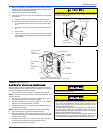
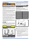
• If the suction line is 3/4" diameter - position the bulb near the top
of the copper tube as shown. If the tube is 7/8" diameter - position
the bulb near the bottom of the tube. Refer to Figure 7.
• Wrap the clamp, bulb & line securely with insulation provided.
NOTE: The coil should be open to the air for no more than 2 minutes to
keep moisture and contaminates from entering the system. If the coil
cannot be brazed into the refrigeration system in that time, the ends
should be temporarily closed or plugged. For a short term delay, use
masking tape over the ends of the copper tubing to close the tube to the
air. For a longer term delay, use plugs or caps. There is no need to
purge the coil if this procedure is followed.
REFRIGERANT LINE CONNECTION
See the outdoor unit installation instructions for the procedure to install
field supplied tubing for systems with sweat fittings.
Stub adapters are available to adapt sweat connections to quick con-
nections.
Connect lines as follows:
NOTE: Route the refrigerant lines to the coil in a manner that will not
obstruct service access to the coil, air handling system or filter.
1. Suction line connections are made outside the center access
panel. Center access panel is recessed to assure sufficient room
for brazing or it can be removed and slid over the suction line dur-
ing brazing.
2. Plan for TXV bulb placement.
3. Remove rubber plugs from refrigerant lines.
4. Braze the suction line. Re-attach the center access panel, if it had
been removed.
5. Braze the liquid line.
6. Install supplied grommets on both the suction and liquid lines to
complete the air seal.
7. See previous section for TXV bulb.
Lines should be sound isolated by using the appropriate hangers or
strapping.
When field supplied lines are used be sure to insulate the suction line
only.
ELECTRIC HEATERS & OPERATING CON-
TROLS
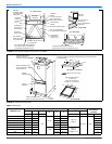
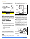
The low voltage transformer and fan / heater control, are standard on all
models. See Figure 8. The air handlers are shipped pre-wired to oper-
ate as cooling only applications. To complete the installation for cooling
only, install the 6-pin jumper plug to the control board to bypass the
heater limit controls. This jumper plug is secured to the duct cover near
the 4-pin power plug harness. Failure to install the plug will cause the
blower to run continuously. (See Figure 8).
Mark the unit nameplate with the appropriate heater selection on the
space provided or NONE to indicate cooling only. To operate these units
with electric heat, it is necessary to field install an electric heater kit
(2HK). See Electric Heater Kit Accessory Installation instructions for
proper installation procedure. Prior to installing electric heat, it is neces-
sary to perform the following procedure:
1. Remove the 4-pin power plug from the control board (See Figure
8).
NOTE: This pin must not be used when electric heaters are installed.
2. Remove the four (4) screws from the duct cover and remove the
duct cover from the air handler.
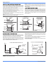
Right-hand Airflow Application Only - Models with Circuit
Breakers - See Figure 9
If unit is to be installed for right hand air flow, the circuit breakers in the
heat kit will need to be removed and rotated 180°, so the OFF position
will be down when the cabinet is positioned on the right side. This is an
NEC requirement. Do One Breaker At A Time - to make sure wires
are reconnected properly. Loosen terminal screws on the wires and
gently pull the wires back from the breaker. Remove screws securing
the breaker plate and rotate 180°, then secure the breaker plate and
reconnect the wires to the breaker. Proper torque for terminal screws is
35 in/lbs.
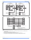
FIGURE 7: Bulb Location
COIL UNDER PRESSURE.
Relieve pressure by removing plug from piping connection. Coil will
have factory installed TXV. See outdoor unit documentation for cor-
rect TXV to be used. Refer to unit nameplate for TXV identification
for this unit.
*
ROTATE BULB TO KEEP
TAILAT BOTTOM
TAIL
END
UP
VERTICAL
RISER
FIGURE 8: Control Board
FIGURE 9: Electric Heaters in Horizontal Configuration - Right Hand
Air Flow
R
Y
G
W2
W1
O C
2
4
V
A
C
BREAK TAB FOR
VARIABLE SPEED MOTOR
L
2
F
A
N
L
1
L
2
L
1
L2
H
L
L
1
2
3
4
K2
T9A
K1
T9A
5
A
M
P
M
A
X
2 SPEED LTRIPECM
FAN
&
LIM
PWR
LIM
&
HEAT
COM
TEST
HEAT 2
DRV
HEAT 4
DRV
HEAT 3
DRV
FAN RELAY
FAN CONNECTIONS
TRANSFORMER
CONNECTIONS
(HIGH VOLTAGE)
4-PIN POWER
CONNECTOR
1 STAGE
HEAT RELAY
24 VOLT R
5AMP
CONTROL
VOLTAGE
FUSE
6-PIN CONNECTOR
(LIMIT, 2ND, 3RD
& 4TH HEAT RELAY
DRIVER)
24 VOLT
COMMON
HEAT KITASSEMBLY
REMOVE 3 SCREWS TO
REMOVE THE CIRCUIT
BREAKER BRACKET
FROM HEAT KITASSEMBLY
JUMPER BAR
JUMPER BAR COVER
FIELD SUPPLY WIRING
WILL BEATTACHED TO
THIS SIDE OF THE
CIRCUIT BREAKER(S)
CIRCUIT BREAKER(S) - THERE
MAY BE ONE, TWO ORTHREE
CIRCUIT
BREAKER
BRACKET
HEAT KIT WIRING WILLBE
ATTACHED TO THIS SIDE OF
THE CIRCUIT BREAKER(S)
AIRFLOW


