


PQ410-4
161-048978-001
JULY, 2009
4 CES
SERVICE MANUAL
(Supersedes PQ410-3)
Electric Fluid Heat Transfer Systems
© 2010 Chromalox, Inc.
GENERAL
This Service Manual is furnished as an aid to help start-up and
service Chromalox Heat Transfer Systems. Listed below are con-
ditions which could occur during start-up and operation.
CAUTION: Hazard of Electric Shock. Any installa-
tion involving electricity must be grounded to earth
to eliminate shock hazard.
1. USE THE RIGHT HEAT TRANSFER FLUID
DO read manufacturer’s technical bulletins and instructions care-
fully. Some heat transfer fluids may ignite or burn spontaneously
if not properly used.
Chromalox Fluid Heat Transfer Systems are designed for a par-
ticular heat transfer fluid or a class of heat transfer fluids. If you
are not sure you are using an accepted heat transfer fluid, check
with your local Chromalox sales and application engineering
office listed on back cover or consult Chromalox Bulletin PQ301
for the correct heat transfer fluid.
DO NOT
mix heat transfer fluids unless authorized and approved
by the fluid manufacturer.
All heat transfer fluids are not compatible with each other,
whether made by the same manufacturer or a different manufac-
turer. If you plan to switch fluids, check with the fluid manufac-
turer to determine the following.
A. Is the new fluid compatible with the old?
B. What is the recommended cleaning method to remove the old
fluid, its sludge, or any deposits remaining in the system?
C. Does the fluid manufacturer have a reclaiming service for used
fluid? Do they have a recommended procedure for disposal of
used or old fluid?
CAUTION: To avoid possible damage to the heaters
do not energize the heater unless the system is
filled with fluid.
DO
provide for expansion and contraction of process piping and
connections to the system. Piping strains can cause pump and
motor mis-alignment, excessive wear on pump body, bearings and
stuffing box packing or mechanical seal and will eventually cause
failure of the pump and system.
Piping should be properly supported so pump can be removed
without changing the position of the piping. If piping moves when
the pump is removed, pump malfunction is probably due to stress-
es and twisting caused by the piping. These stresses will multiply
when the system is hot due to thermal expansion.
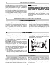
DO
provide sufficient cross sectional area in the process piping
connections equivalent to the system pipes. In order to prevent
undue pressure drop, maximum velocity in all piping should be
less than 10 feet per second.
DO NOT
use process piping connections smaller than the pipes
used in the system.
If there is a high differential pressure between the inlet and out-
let of the heat transfer system at operating temperature, this is
probably due to a piping restriction. A continuing high differential
pressure can cause excessive wear on the pump and pump stuffing
box packing or mechanical seal and will eventually cause prema-
ture failure of the pump. The major causes of restrictions are:
A. Inlet and outlet pipes smaller than provided on the system.
B. Piping many processes in series with one another. To reduce
the pressure drop of the system, equipment should be re-piped
in balanced parallel flow.
2. PIPE STRAIN
3. PIPING RESTRICTIONS