GENERAL
INSTALLATION
© 2010 Chromalox, Inc.
Chromalox Type GCHMT Circulation Heater For
Steam, Gas and Air Heating
DANGER:
This heater is not intended for use in hazardous
atmospheres where flammable vapors, gases, liquids, or
other combustible atmospheres are present as defined in
the National Electric Code. Failure to comply can result in
explosion or fire.
Hazardous area terminal enclosures are available, consult your
local Chromalox representative for details.
The GCHMT series is a general-purpose gas or steam circula-
tion heater intended for use indoors.
The 3 incoloy-sheathed tubular elements are centered in a 3”
diameter steel heating chamber and welded to a removable screw
plug. The assembly is surrounded by 1-1/2” insulation and sheet
metal jacket.
Depending upon the specifications, the GCHMT may or may
not be factory equipped with AR or other Chromalox thermostats.
Such thermostats function to control outlet temperatures under
abnormal flow condition. These controls do not fail-safe.
WARNING:
Users should install adequate back-up controls
and safety devices with their electric heating equipment.
Where the consequences of failure may be severe, back-up
controls are essential. Although the safety of the installation
is the responsibility of the user, Chromalox will be glad to
make equipment recommendations.
WARNING:
Hazard of electric shock. Disconnect all power
before installing heater.
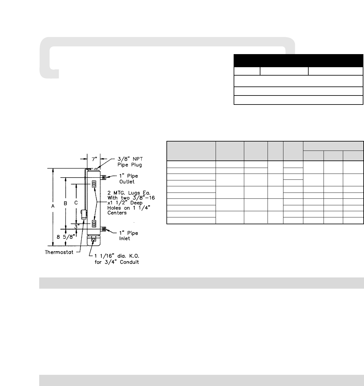
1. Vertical mounting (axis of chamber vertical as in sketch
above) is preferred. Check factory for recommendations on hori-
zontal mounting.
2. To avoid excess temperatures at electrical wiring, mount
heater with terminal enclosure at bottom, and use lower nozzle as
inlet to the circulating steam, air, or gas.
3. The GCHMT series of circulation heaters are provided with
mounting lugs to support the heater chamber. Refer to sketch
above for location of these mounting lugs.
4. Mount heaters to permit unrestrained expansion of chamber
due to temperature. This can be accomplished by using a slotted
mounting assembly on either of the lugs.
5.
DANGER:
Hazard of fire.
Provide minimum of 6” spacing
from a chamber and related piping to nearest combustible materi-
al. Avoid operation of heater near combustible fluids or in com-
bustible vapor or gas laden atmosphere.
6. Provide adequate space at terminal end to permit withdrawal
of the heater from chamber should servicing be required.
7. If two or more heaters are needed to provide the needed heat-
ing capacity, arrange them for series gas or vapor flow.
8.
DANGER:
Possible explosion.
A pressure relief valve
should be provided by customer at outlet of vessel. There should
be no other valving between vessel and valve.
Watts Dimensions (in.)
Catalog Per
Number Voltage Phase KW Sq.In. A B C
GCHMT-30105 120 1
1
15
20-1/2 9-3/8 —
GCHMT-3105 240 or 480 1 or 3 23
GCHMT-30305
1 or 3 3
15
30-5/8 22-1/2 16-1/2
GCHMT-3305
240 or 480
23
GCHMT-30505
1 or 3 5
15 56-3/8 45-1/4 39-1/4
GCHMT-3505
240 or 480
23 30-5/8 22-1/2 16-1/2
GCHMT-30755
1 or 3 7.5
15 67-1/8 56 50
GCHMT-3075
240 or 480
23 56-3/8 45-1/4 39-1/4
GCHMT-30905
1 or 3 9
15 78-1/8 67 61
GCHMT-3905
240 or 480
23 56-7/8 45-1/4 39-1/4
Specifications — Table A
WARNING: Safe operating conditions depend on operating pressure, mass velocity
of gas and discharge temperature of the gas. At a given discharge gas temperature
heater element sheath temperature, and pipe body temperature tend to increase as gas
flow (mass velocity) decreases. The standard GCHMT has a 750˚F limitation on the
carbon steel body and a 1500˚F limit on the incoloy sheath elements. Check factory if
any doubt exists as to temperatures that will be encountered in your specific applica-
tion. A stainless steel body is required at pipebody temperatures above 750˚F.
(Std.)
(Std.)