


FIRE/EXPLOSION HAZARD. This heater is not intend-
ed for use in hazardous atmospheres where flamma-
ble vapors, gases, liquids or other combustible atmos-
pheres are present as defined in the National
Electrical Code. Failure to comply can result in per-
sonal injury or property damage.
The NWH-JR is a compact water circulation heater ideally
suited for use as an engine coolant water heater and for many other
uses where on-the-spot hot water is required.
The copper-sheathed tubular heating element is centered in a
galvanized iron or brass pipe body. Its screw-plug type mounting
provides easy removal when necessary. The assembly is surround-
ed by insulation and a sheet metal jacket.
An integral 60-180°F range thermostat is provided to control
outlet temperatures. However, this control does not fail-safe.
The system designer is responsible for the safety of
this equipment and should install adequate back-up
controls and safety devices with their electric heating
equipment. Where the consequences of failure could
result in personal injury or property damage, back-up
controls are essential.
(Supersedes PE404-7)
PE404-8
NWH
161-048467-001
APRIL, 2005
4
and
Installation, Operation
RENEWAL PARTS IDENTIFICATION
NWH-JR Circulation Heater For Water Heating
© 2010 Chromalox, Inc.
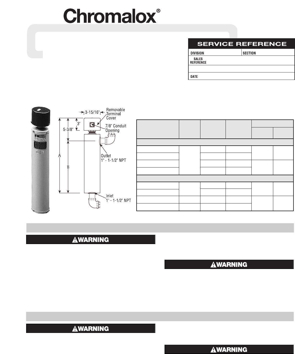
Dimensions (In.)
Watt
Model Volts kW Density A B
Galvanized Iron Construction
NWHJRG-01-01P5-E1 120 1.5 82
18 12-3/8
NWHJRG-01-002P-E1
or
283
NWHJRG-01-02P5-E1 2.5 78
NWHJRG-01-003P-E1 240 3 78
22 16-3/8
Brass Construction
NWHJRB-01-01P5-E1 120 or 1.5 82
18 12-3/8
NWHJRB-01-002P-E1 240 2 83
NWHJRB-01-02P5-E1 240 2.5 78
NWHJRB-01-003P-E1 240 3 78
22 16-3/8
Specifications – Table A
GENERAL
INSTALLATION
ELECTRIC SHOCK HAZARD. Disconnect all power
before installing or servicing heater. Failure to do so
could result in personal injury or property damage.
Heater must be installed by a qualified person in accor-
dance with the National Electrical Code, NFPA 70
1. The NWH-JR circulation heater should be mounted vertically with
the terminal enclosure at the top. No additional support other than
the connecting pipes is needed.
2. Make piping connections to either new or existing plumbing at the
1 x 11-1/2” NPT threaded inlet and outlet as shown above.
3. If foreign material is to be carried by the liquid flow, install suit-
able filters in the inlet pipe to the heater.
4. Provide adequate space at terminal end to permit withdrawal of the
heater from chamber should servicing be required.
FIRE HAZARD. Since heaters are capable of develop-
ing high temperatures, extreme care should be taken
to:
A. Provide a minimum of 6” spacing from chamber and related
piping to nearest combustible material.
B. Do not heat combustible materials.
Figure 1